


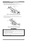
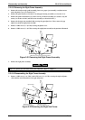
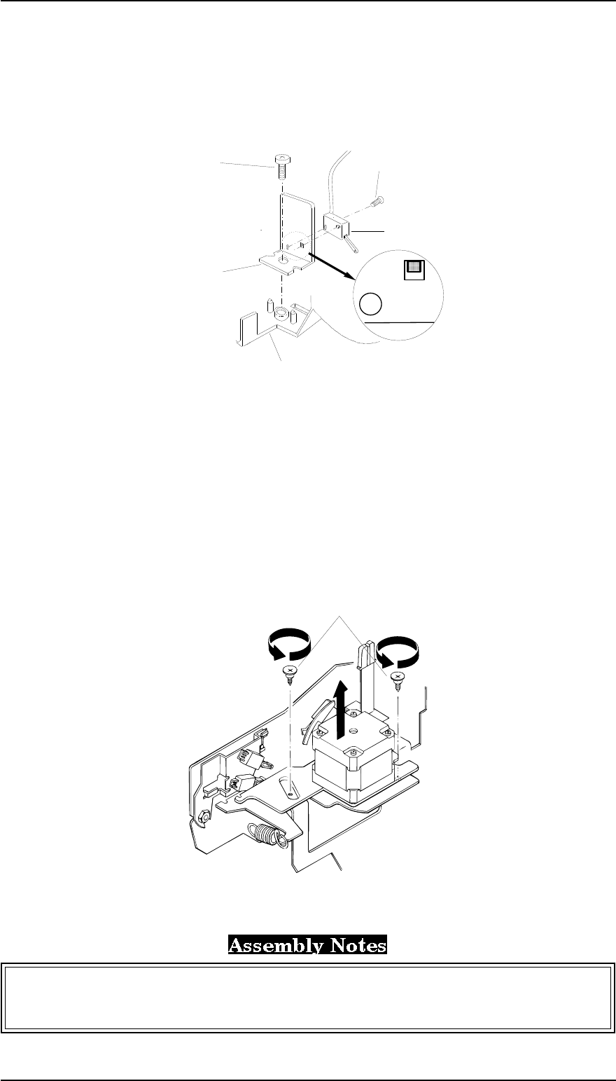
3.2.8 Removing the Case Open Sensor Assembly
1. Remove the rear edge guide assembly, paper eject assembly, rear tractor unit, and printer cover
(see Section 3.2.1).
2. Remove the panel board (see Section 3.2.2) and upper housing assemblies (see Section 3.2.7).
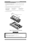
3. Turn the upper housing assembly over and remove the case open sensor assembly by loosening
the CBB screw ( 3 × 8, F/Zn) fixing the sensor holder to the upper housing assembly.
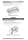
3.2.9 Removing the CR Motor Assembly
1 Remove the rear edge guide assembly, paper eject assembly, rear tractor unit, and printer cover.
(see Section 3.2.1).
2. Remove the panel board (see Section 3.2.2) and upper housing assemblies (see Section 3.2.7).
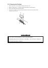
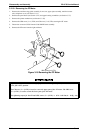
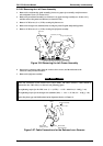
3. Remove the 2 CR mounting screws securing the CR motor assembly. After releasing the
extension spring (15.7 g), disengage the timing belt from the CR motor assembly.
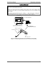
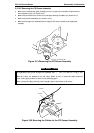
4. Disconnect the cable for CN11 from the C166 MAIN board assembly.
5. Remove the CR motor assembly from the printer mechanism.
The tightening torque for the 2 CR mounting screws = 0.78 ~ 0.98 Nm (8~10 Kg - cm)
Adjust the bidirectional print alignment. Refer to Chapter 4.
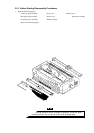
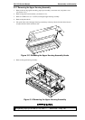
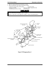
C.B.B. Screw
(3x8 F/Zn)
C.B.Screw
(2 x8 F/Ni)
Sensor
Holder
Case Open
Sensor Assembly
Upper Housing Assembly
Figure 3-15 Removing the Case Open Sensor Assembly
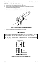
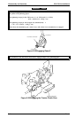
CR Mounting Screws
Figure 3-16 Removing the CR Motor Assembly
Disassembly and Assembly FX-2170 Service Manual
3-12 Rev.A