


3.2.10.2 Removing the PG Sensor Assembly
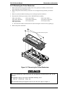
1. Remove the rear/front edge guide assembly, front cover, paper eject assembly, rear/front tractor
unit, and printer cover (see Section 3.2.1).
2. Remove the panel board (see Section 3.2.2) and upper housing assemblies (see Section 3.2.7).
3. Remove the printer mechanism (see Section 3.2.10 ).
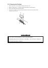
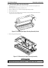
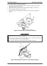
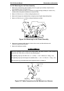
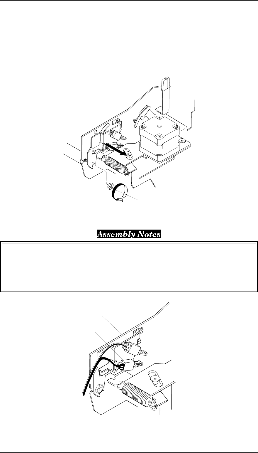
4. Remove the hexagon nut (standard, M4) securing the PG sensor assembly to the right frame
assembly.
The tightening torque for the hexagon nut (standard, M4) = 1.18 ~ 1.37 Nm (12 ~ 14 Kg f - cm)
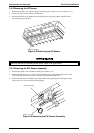
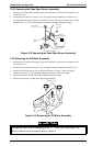
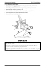
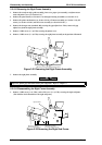
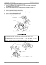
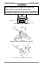
When the sensors are mounted to the PG sensor holder be sure to mount the white connector’s
sensor in the upper position as shown in the following figure.
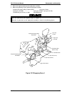
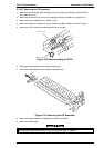
When securing the shaft, push the front CR guide shaft to the bottom of the cutout.
PG SW1
PG SW2
Figure 3-20 Mounting the Cables for the PG Sensor Assembly
Hexagon Nut (Standard, M4)
Figure 3-19 Removing the PG Sensor Assembly
FX-2170 Service Manual Disassembly and Assembly
Rev.A 3-15