


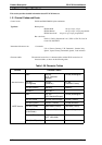
1.3.2.2 Parallel Interface (Reverse Channel)
Transmission mode IEEE-P1284 nibble mode
Adaptable connector 57-30360 (Amphenol) or equivalent
Synchronization Refer to the IEEE-P1284 Specification
Handshaking Refer to the IEEE-P1284 Specification
Signal level TTL-compatible (IEEE-P1284 level 1 device)
Data transmission timing Refer to the specification
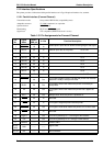
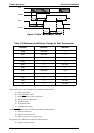
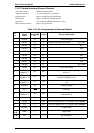
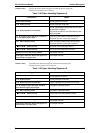
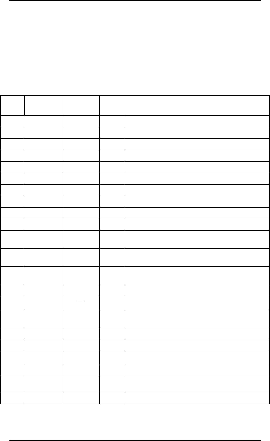
Table 1-33 Pin Assignments for Reverse Channel
Pin
No,
Signal
Name
Return GND
Pin
In /Out Function Description
1
HostClk 19 In Host clock signal.
2
DATA1 20 In Parallel input data to the printer bit 0: LSB
3
DATA2 21 In bit 1
4
DATA3 22 In bit 2
5
DATA4 23 In bit 3
6
DATA5 24 In bit 4
7
DATA6 25 In bit 5
8
DATA7 26 In bit 6
9
DATA8 27 In bit 7: MSB
10
PtrClk 28 Out Printer clock signal.
11
PtrBusy /
DataBit-3, 7
29 Out
Printer busy signal and reverse channel transfer of data
bits 3 or 7
12
AckDataReq/
DataBit-2, 6
28 Out
Acknowledge data request signal and reverse channel
transfer of data bits 2 or 6
13
Xflag /
DataBit-1, 5
28 Out
X-flag signal and reverse channel transfer of data bits 1
or 5
14
HostBusy 30 In Host busy signal.
31
INIT
30 In Not used.
32
DataAvail /
DataBit-0, 4
29 Out
Data available signal and reverse channel transfer of
data bits 0 or 4
36
1284-Active 30 In 1284 active signal.
18
Logic H —— Out
This line is pulled up to + 5 V through 3.3K Ω resistor.
35
+5 V —— Out
This line is pulled up to +5 V through 3.3K Ω resistor.
17
Chassis —— —— Chassis GND.
16, 33,
19-30
GND —— —— Signal GND.
15, 34
NC —— —— Not connected.
FX-2170 Service Manual Product Description
Rev.A 1-23