


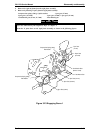
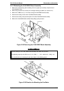
3.2.12 Removing the C166 PSB/E Board Assembly
1. Remove the rear/front edge guide assembly, front cover, paper eject assembly, rear/front tractor
unit, and printer cover.
2. Remove the panel board (see Section 3.2.2) and upper housing assemblies (see Section 3.2.7).
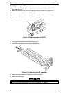
3. Remove the 5 CBB screws (3 × 12, F/Zn) securing the C166 PSB/E board assembly.
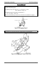
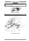
4. Disconnect the cable for CN3 on the C166 MAIN board assembly.
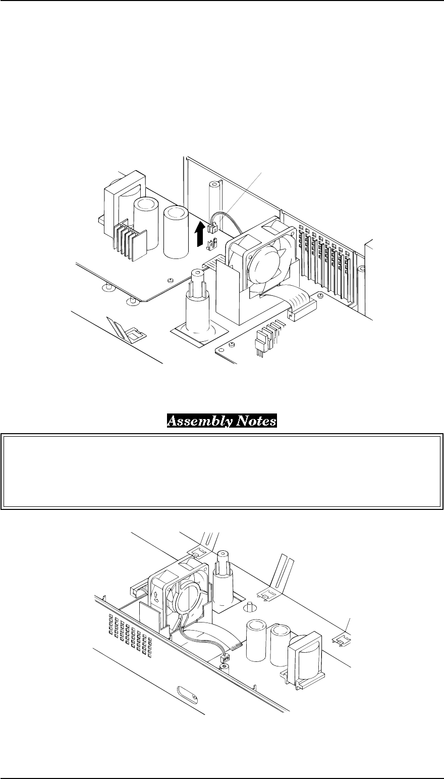
5. Disconnect the cable for the fan motor from CN3 on the C166 PSB/E board assembly.
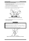
6. Remove the C166 PSB/E board assembly while pulling up the fan motor.
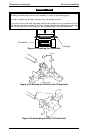
Insert the cable for CN2 (C166 PSB/E board assembly side) under the fan motor.
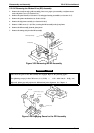
The tightening torque for the CBB screw (3 × 12, F/Zn) = 0.78 ~ 0.98 Nm (8 ~ 10 Kg - cm)
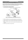
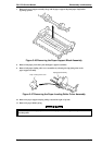
Notice the direction for mounting the fan motor. Refer to the following figure.
CN3 Connector
Figure 3-38 Removing the C166 PSB/E Board Assembly
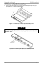
Figure 3-39 Direction for Mounting the Fan Motor
FX-2170 Service Manual Disassembly and Assembly
Rev.A 3-25