


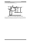
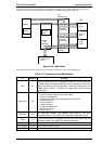
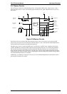


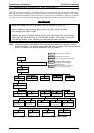

2.3.7 Sensor Circuits
The CPU detects conditions of the following sensors: home position (HP) sensor, release sensors 1 and 2,
platen gap (PG) sensors 1 and 2, rear and front paper end (PE) sensors, paper width (PW) sensor, and cover
open sensor.
Two types of sensors are used in this printer. Release sensors 1 and 2 , PG sensors 1 and 2, the front PE
sensor, and cover open sensor are momentary switches. Pages 2-3 and 2-4 describe the relationship between
release and PG sensor operation and actual print operation.
The other type of sensor is used for the HP sensor, rear PE sensor, and PW sensor, which are photo diode
switches. The HP sensor detects CR home position when the photo diode rays are cut off by the printhead.
The rear PE sensor detects that paper has been loaded when the photo diode rays are cut off by the sensor
plate, which is included in the rear PE sensor. The PW sensor, used for paper width measurement and paper
loading positioning, detects the paper edge by comparing the measured voltage with standard voltage, which
was measured during the power on sequence.
Additionally, as mentioned on the page 2-24, the +35 V line and head temperature are monitored to set the
pulse length of the head drive signal.
CPU
P36
P40
AN2
P53
P32
P33
P34
P35
+5V
+5V
PG Sensor 2
PG Sensor 1
Release
Sensor 1
Release
Sensor 2
+5V
+5V
+5V
+5V
HP Sensor
+5V
+5V
Rear PE
Sensor
+5V
Front PE
Sensor
+5V
+5V
PW Sensor
INT7
+5V
Cover Open
Sensor
18
67
66
65
64
76
75
68
70
Figure 2-38 Sensor Circuits
FX-2170 Service Manual Operating Principles
Rev.A 2-27