


Installation and Getting Started Guide
HP9300(config-lbif-1)# ip address 10.0.0.1/24
Syntax: interface loopback <num>
The <num> value can be from 1 – 8.
Syntax: [no] ip address <ip-addr> <ip-mask> [secondary]
or
Syntax: [no] ip address <ip-addr>/<mask-bits> [secondary]
USING THE WEB MANAGEMENT INTERFACE
1. Log on to the device using a valid user name and password for read-write access. The System configuration
panel is displayed.
2. Select the IP Address
link to display a table listing the configured IP addresses.
3. Select the Loop Back
link.
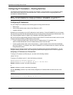
NOTE: If the device already has loopback interfaces, a table listing the interfaces is displayed. Click the
Modify button to the right of the row describing an interface to change its configuration, or click the Add Loop
Back link to display the Router Loop Back configuration panel.
4. Select the loopback interface number from the Loopback field’s pulldown menu. You can select from 1 – 8.
5. Select the status. The interface is enabled by default.
6. Click Add to add the new interface.
7. Click on Configure in the tree view to display the configuration options.
8. Click on IP to display the IP configuration options.
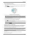
9. Select the Add IP Address
link to display the Router IP Address panel.
10. Select the loopback interface from the Port field’s pulldown menu. For example, to select loopback interface
1, select “lb1”. (If you are configuring a Chassis device, you can have any slot number in the Slot field.
Loopback interfaces are not associated with particular slots or physical ports.)
11. Enter the loopback interface’s IP address in the IP Address field.
12. Enter the network mask in the Subnet Mask field.
13. Click the Add button to save the change to the device’s running-config file.
14. Select the Save
link at the bottom of the dialog. Select Yes when prompted to save the configuration change
to the startup-config file on the device’s flash memory.
Assigning an IP Address to a Virtual Interface
A virtual interface is a logical port associated with a Layer 3 Virtual LAN (VLAN) configured on a routing switch.
You can configure routing parameters on the virtual interface to enable the routing switch to route protocol traffic
from one Layer 3 VLAN to the other, without using an external router.
1
You can configure IP, IPX, or AppleTalk routing interface parameters on a virtual interface. This section describes
how to configure an IP address on a virtual interface. Other sections in this chapter that describe how to configure
interface parameters also apply to virtual interfaces.
NOTE: The routing switch uses the lowest MAC address on the device (the MAC address of port 1 or 1/1) as the
MAC address for all ports within all virtual interfaces you configure on the device.
1.HP’s feature that allows routing between VLANs within the same device, without the need for external rout-
ers, is called Integrated Switch Routing (ISR). See “Integrated Switch Routing (ISR)” on page 16-3.
6 - 20