


Installation and Getting Started Guide
H6
192.168.2.155
H5
192.168.2.193
H4
192.168.2.175
H9
H3
192.168.1.218
H2
192.168.1.170
H1
192.168.7.1
H8H7
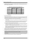
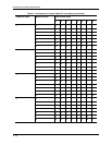
IP Forwarding Cache
Host-Based Load Sharing
Destination Host
192.168.1.170 (H1)
192.168.1.234 (H2)
192.168.1.218 (H3)
192.168.2.175 (H4)
192.168.2.193 (H5)
192.168.2.155 (H6)
192.168.3.209 (H7)
192.168.3.159 (H8)
192.168.3.111 (H9)
Next-Hop
192.168.6.2 (R2)
192.168.5.1 (R3)
192.168.6.2 (R2)
192.168.5.1 (R3)
192.168.6.2 (R2)
192.168.5.1 (R3)
192.168.6.2 (R2)
192.168.5.1 (R3)
192.168.5.1 (R2)
192.168.1.1
192.168.2.1
192.168.3.1
192.168.7.2
192.168.4.1
192.168.6.2
192.168.5.2
192.168.4.2192.168.5.1
192.168.1.234
192.168.6.1
R4
R3
R2
R1
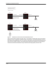
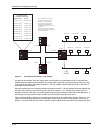
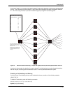
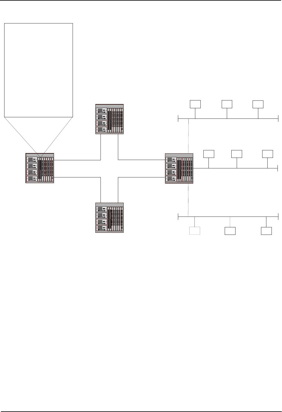
R1 is configured with four IP load
sharing paths, and has two paths
to hosts H1 - H9, attached to R4.
The cache entries in this example
are based on the assumption that
R1 receives traffic for hosts in H1 - H9
in that order.
Once a packet for host H1 is received,
the cache entry applies to all traffic for H1.
Thus, R2 is always used.
192.168.3.209 192.168.3.159 192.168.3.111
Figure 6.5 Host-based IP load sharing – basic example
As shown in this example, when the routing switch receives traffic for a destination and the IP route table has
multiple equal-cost paths to that destination, the routing switch selects the next equal-cost path (next-hop router)
in the rotation and assigns that path to destination. The path rotation is determined by the order in which the IP
route table receives the paths.
Since the configuration in this example contains two paths to hosts H1 – H9, the software alternates between the
two paths when creating new load sharing cache entries for hosts H1 – H9. So long as the cache entry for a
destination remains in the cache, the routing switch always uses the same path for the traffic to the destination. In
this example, the routing switch always uses R2 as the next hop for forwarding traffic to H1.
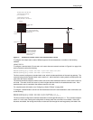
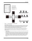
Figure 6.6 shows another example of IP forwarding cache entries for the configuration shown in Figure 6.5. The
network and load sharing configurations are the same, but the order in which R1 receives traffic for the host is
different. The paths differ due to the order in which the routing switch receives the traffic for the destination hosts.
6 - 52