


Advanced Configuration and Management Guide
EXAMPLE:
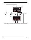
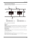
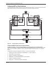
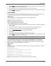
To define and assign the virtual router IP addresses for Router 1, shown in Figure 13.5, you would need to define
two separate virtual IP addresses for interfaces A and C as well as linking those address to the IP addresses of
the physical interfaces for A and C.
For purposes of this example we are assuming that interface A corresponds to physical interface 1/7 and interface
C corresponds to physical interface 2/1.
To enable SRP on an interface:
1. Log on to the device using a valid user name and password for read-write access. The System configuration
dialog is displayed.
2. Click on the plus sign next to Configure in the tree view to expand the list of configuration options.
3. Click on the SRP link.
• If the device does not have an SRP configuration, the SRP configuration panel is displayed.
• If SRP is already configured but you are adding a new SRP configuration, click on the Add Interface
link
to display the SRP configuration panel.
• If you are modifying an existing SRP configuration, click on the Modify button to the right of the row
describing the configuration to display the SRP configuration panel.
4. Select the IP address to be configured from the IP Address field’s pull down menu. For example, if you are
initially assigning SRP to interface A (Router 1) as shown in Figure 13.5, select IP address 192.53.5.2.
5. Assign a virtual IP address for the virtual router. A virtual router IP address needs to be configured on at least
one router in the SRP group. For interface A, you would assign 192.53.5.1, as shown in the network
configuration of Figure 13.5.
NOTE: The default IP address for a virtual router is 0.0.0.0.
6. Enter the other router IP address. This is the physical IP address of the partner router’s interface in the
active-standby router relationship. Notice that in the case of the example (Figure 13.5), interface B on router
2 is designated as the standby router interface so IP address 192.53.5.3 is entered.
7. To establish a router as the active router in the redundancy configuration, a higher value should be entered
for its preference level. In this case, because router 1 is the desired active router and the router currently
being configured, a value of 200 is entered.
8. Modify the keep alive time parameter if a value other than the default value of 3 seconds is desired. For this
configuration, modify the value to 15.
NOTE: The keep alive time parameter allows the user to modify how often the SRP hello message is sent
on an interface. Possible values are 1 – 120 seconds. The default is 3 seconds.
NOTE: The keep alive time parameter must be set to the same value on both the active and standby routers
when both routers are connected to the same sub-net.
9. Modify the dead time parameter if a value other than the default value of 9 seconds is desired. For this
configuration you would modify the value to 30.
NOTE: The dead time parameter allows you to define the period of time (hold time) that the standby router
will wait before determining that the active router is unavailable (dead). When the configured period of time
expires, the standby router will become active. Possible values are 3 – 255. The default value is 9 seconds.
NOTE: The dead time parameter must be set to the same value on both the active and standby routers
when both routers are connected to the same sub-net.
13 - 12