


Configuring SRP
Assign Virtual Router IP Addresses
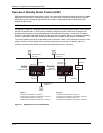
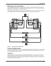
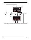
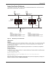
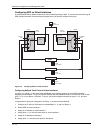
In the examples in this section, SRP is used to provide a redundant path between Host 1 and Host 3 to ensure
against failure of the primary path. See Figure 13.5.
Host 1 Host 2
Virtual
Router
Router 1
Router 2
Default Router
192.53.5.1
192.53.5.1 192.53.5.1 192.53.5.1
Default Router
192.53.5.1
192.53.5.2
192.53.5.3
(A)
(B)
Default Router
192.55.4.1
192.55.4.1 192.55.4.1192.55.4.1
Preference = 200
Active
Preference = 60
Standby
192.55.4.2 192.55.4.3
(C)
(D)
Host 3
Router 1:
Router 2:
IP Address for Interface A: 192.53.5.2
Virtual Router IP address for Interface A: 192.53.5.1
IP Address for Interface B: 192.53.5.3
Virtual Router IP address for Interface B: 192.53.5.1
IP Address for Interface C: 192.55.4.2
Virtual Router IP address for Interface C: 192.55.4.1
IP Address for Interface D: 192.55.4.3
Virtual Router IP address for Interface D: 192.55.4.1
Figure 13.5 SRP operating in an HP 9304M network
USING THE CLI
EXAMPLE:
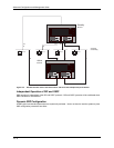
To define and assign the virtual router IP addresses for Router 1, shown in Figure 13.5, you would need to define
two separate virtual IP addresses for interfaces A and C and link those addresses to the IP addresses of the
physical interfaces for A and C.
This example assumes that interface A corresponds to physical interface 1/7, and interface C corresponds to
physical interface 2/1.
Configuring Router 1
To establish the virtual IP address 192.53.5.1 for interface A defined by IP address 192.53.5.2 and Ethernet port
1/7, enter the following commands:
Router1(config)# inter e 1/7
Router1(config-if-1/7)# ip srp address 192.53.5.2 vir-rtr-ip 192.53.5.1
other-rtr-ip 192.53.5.3
Notice that the latter command also defines the other routing switch used in this configuration by entering the IP
address for Interface B on Router 2 (other-rtr-ip 192.53.5.3).
13 - 9