


Advanced Configuration and Management Guide
The following command saves all the configuration changes above to the routing switch’s startup-config file on
flash memory. The routing switch applies NAT configuration information as soon as you enter it into the CLI.
Saving the changes to the startup-config file ensures that the changes are reinstated following a system reload.
HP 9304M or HP 9308M(config)# write memory
Private NAT Clients Connected Directly to the routing switch
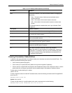
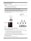
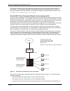
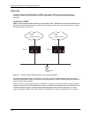
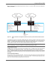
Figure 11.3 shows an example of a NAT configuration in which the NAT clients on the private network are directly
connected to the routing switch. The configuration commands are similar to those for the configuration in “Private
NAT Clients Connected to the routing switch by a switch” on page 11-14, except the inside NAT and outside NAT
interfaces are virtual routing interfaces (called virtual interfaces or ”VEs”) instead of physical ports.
Since all the clients are in the same sub-net, the routing switch is configured with a virtual interface to serve as the
inside NAT interface, the routing switch’s IP interface for the NAT clients who have private addresses.
The virtual interface is required because you cannot configure IP addresses in the same sub-net on multiple
physical interfaces on the routing switch. A virtual interface is a logical interface that allows you to associate the
same IP address (the IP address of the virtual interface) with multiple physical ports.
You can use a virtual interface for routing only when you add the interface to a port-based VLAN. A port-based
VLAN is a separate Layer 2 broadcast domain, a logical switch within the HP device. The routing switch uses
virtual interfaces to route Layer 3 traffic between port-based VLANs. Thus, this configuration also includes
configuration of separate port-based VLANs for the clients’ inside NAT interface and for the outside NAT interface.
63.251.295.1/26
Internet
The device performs NAT
for traffic between the outside
NAT interface and the inside
NAT interface.
NAT Pool = 63.251.295.47/26 - 63.251.295.48/26
Internet
access router
8/9
8/16
8/24
1/1
Outside NAT interface
8/1
10.10.10.2
Virtual interface 15
63.251.295.46/26
10.10.10.3
10.10.10.4
Inside NAT interface
Virtual interface 10
10.10.10.50/26
10.10.10.5
Figure 11.3 NAT clients connected directly to the routing switch
Here are the CLI commands for implementing the NAT configuration shown in Figure 11.3. These commands
configure the following:
• Port-based VLAN 2 and virtual interface 10 for the inside NAT interface
• Port-based VLAN 3 and virtual interface 15 for the outside NAT interface
• An Access Control List (ACL) for the range of private address in the private network on virtual interface 10
11 - 16