


Advanced Configuration and Management Guide
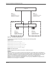
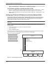
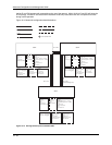
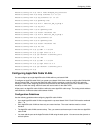
the flat IP and IPX segment with connectivity to the rest of the network. Within VLAN 4 IP and IPX will follow the
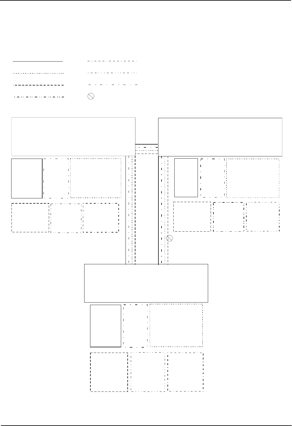
STP topology. All other IP sub-nets and IPX networks will be fully routed and have use of all paths at all times
during normal operation.
Figure 16.12 shows the configuration described above.
VLAN 2
VLAN 6
VLAN 3
VLAN 7
VLAN 4
VLAN 8
= STP blocked VLAN
VLAN 7
Port 26 (tagged)
VE 6
-IP sub-net 8
-IPX network 8
VLAN 2
Ports 1 - 4
VE 1
-IP sub-net 6
VLAN 8
Ports 5 - 8
VE 2
-IPX network 6
VLAN 3
Ports 9 - 16
IP sub-net 7 (ports 9 - 12, VE 3)
IPX network 7 (ports 13 - 16, VE 4)
VE 3
-IP sub-net 7
-OSPF area 0.0.0.0
VE 4
-IPX network 7
VLAN 4
Ports 17 - 24 (untagged)
Ports 25 - 26 (tagged)
VLAN 5
Port 25 (tagged)
VE 5
-IP sub-net 4
-OSPF area 0.0.0.0
-IPX network 4
9304 B
VLAN 6
Port 26 (tagged)
VE 7
-IP sub-net 5
-OSPF 0.0.0.0
-IPX network 5
VLAN 2
Ports 1 - 4
VE 1
-IP sub-net 2
-OSPF area 0.0.0.0
VLAN 8
Ports 5 - 8
VE 2
-IPX network 2
VLAN 3
Ports 9 - 16
IP sub-net 1 (ports 9 - 12, VE 3)
IPX network 1 (ports 13 - 16, VE 4)
VE 3
-IP sub-net 1
-OSPF area 0.0.0.0
VE 4
-IPX network 1
VLAN 4
Ports 17 - 24 (untagged)
Ports 25 - 26 (tagged)
VE 5
-IP sub-net 3
-OSPF area 0.0.0.0
-IPX network 3
VLAN 5
Port 25 (tagged)
VE 6
-IP sub-net 4
-OSPF area 0.0.0.0
-IPX network 4
VLAN 5
VE 4, VE 7
(STP is blocking VE 4)
VE 4, VE 5
VE 4, VE 6
9304 A
9304 C
VLAN 2
VLAN 8
VLAN 3
Ports 1 - 4
Ports 5 - 8
Ports 9 - 16
VE 1
VE 2
IP sub-net 10 (ports 9 - 12, VE 3)
-IP sub-net 9
-IPX network 9
IPX network 10 (ports 13 - 16, VE 4)
-OSPF area 0.0.0.0
VE 3
-IP sub-net 10
-OSPF area 0.0.0.0
VE 4
-IPX network 10
VLAN 4
VLAN 7
VLAN 6
Ports 17 - 24 (untagged)
Port 25 (tagged)
Port 26 (tagged)
Ports 25 - 26 (tagged)
VE 5
VE 6
-IP sub-net 8
-IP sub-net 5
-OSPF area 0.0.0.0
-OSPF area 0.0.0.0
-IPX network 8
-IPX network 5
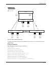
Figure 16.12 Routing between protocol-based VLANs
16 - 22