


Configuring AppleTalk
To configure the defined AppleTalk VLAN virtual interface ve3, enter the following commands:
HP9300(config-if-1/8)# int ve 3
HP9300(config-vif-3)# appletalk cable-range 100 - 100
HP9300(config-vif-3)# appletalk address 100.50
HP9300(config-vif-3)# appletalk zone-name Marketing
HP9300(config-vif-3)# appletalk routing
Routing Between Protocol VLANs Within Port-Based VLANs
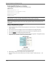
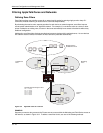
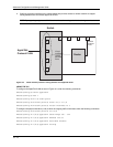
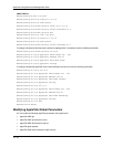
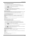
In Figure 15.4, AppleTalk traffic is terminating on ports 1 – 4 on two separate networks, 100 and 200. Suppose
you want to assign these networks to two separate VLANs but would also like to route traffic between the two
VLANs and externally to the routing switch.
To create the configuration shown in Figure 15.4, perform the following tasks.
1. Create port-based VLANs 2 and 3.
NOTE: Protocol VLANs must always be within the boundaries of a port-based domain. Whenever port and
protocol VLANs operate on a system together, you must create the port-based VLAN before you create the
protocol VLAN. The protocol-based VLAN overlays the port-based VLAN.
2. Create AppleTalk protocol VLANs 2 and 3.
3. Configure router interfaces virtual 3 (v3) and virtual 5 (v5).
4. Configure physical interface port 8.
NOTE: Each of the above tasks is described in the following sections.
Switch
Port-based
VLAN 2
AppleTalk
Protocol VLAN
AppleTalk
Protocol VLAN
Port-based
VLAN 3
5 7 8
Router
400.50
Sales
Zone
100.50
Finance
Zone
200.50
Marketing
Zone
Virtual 3
Virtual 5
2
1
4
3
Network 100
Network 200
6
Figure 15.4 Routing between AppleTalk VLANs
15 - 15