


Configuring IP Multicast Protocols
• BSR – The Bootstrap Router (BSR) distributes RP information to the other PIM Sparse routers within the
domain. Each PIM Sparse domain has one active BSR. For redundancy, you can configure ports on multiple
routers as candidate BSRs. The PIM Sparse protocol uses an election process to select one of the candidate
BSRs as the BSR for the domain. The BSR with the highest BSR priority (a user-configurable parameter) is
elected. If the priorities result in a tie, then the candidate BSR interface with the highest IP address is elected.
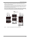
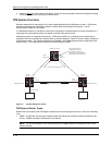
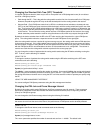
In the example in Figure 9.3, PIM Sparse router B is the BSR. Port 2/2 is configured as a candidate BSR.
• RP – The RP is the meeting point for PIM Sparse sources and receivers. A PIM Sparse domain can have
multiple RPs, but each PIM Sparse multicast group address can have only one active RP. PIM Sparse routers
learn the addresses of RPs and the groups for which they are responsible from messages that the BSR sends
to each of the PIM Sparse routers. In the example in Figure 9.3, PIM Sparse router B is the RP. Port 2/2 is
configured as a candidate Rendezvous Point (RP).
To enhance overall network performance, HP routing switches use the RP to forward only the first packet
from a group source to the group’s receivers. After the first packet, the routing switch calculates the shortest
path between the receiver and source (the Shortest Path Tree, or SPT) and uses the SPT for subsequent
packets from the source to the receiver. The routing switch calculates a separate SPT for each source-
receiver pair.
NOTE: Hewlett-Packard recommends that you configure the same ports as candidate BSRs and RPs.
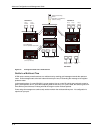
RP Paths and SPT Paths
Figure 9.3 shows two paths for packets from the source for group 239.255.162.1 and a receiver for the group.
The source is attached to PIM Sparse router A and the recipient is attached to PIM Sparse router C. PIM Sparse
router B in is the RP for this multicast group. As a result, the default path for packets from the source to the
receiver is through the RP. However, the path through the RP sometimes is not the shortest path. In this case, the
shortest path between the source and the receiver is over the direct link between router A and router C, which
bypasses the RP (router B).
To optimize PIM traffic, the protocol contains a mechanism for calculating the Shortest Path Tree (SPT) between a
given source and receiver. PIM Sparse routers can use the SPT as an alternative to using the RP for forwarding
traffic from a source to a receiver. By default, HP routing switches forward the first packet they receive from a
given source to a given receiver using the RP path, but forward subsequent packets from that source to that
receiver through the SPT. In Figure 9.3, routing switch A forwards the first packet from group 239.155.162.1’s
source to the destination by sending the packet to router B, which is the RP. Router B then sends the packet to
router C. For the second and all future packets that router A receives from the source for the receiver, router A
forwards them directly to router C using the SPT path.
Configuring PIM Sparse
Limitations in this Release
The implementation of PIM Sparse in the current software release has the following limitations:
• PIM Border Routers (PMBRs) are not supported. Thus, you cannot configure an HP routing interface as a
PMBR interface for PIM Sparse.
• PIM Sparse and regular PIM (dense mode) cannot be used on the same interface.
• You cannot configure or display PIM Sparse information using the Web management interface. (You can
display some general PIM information, but not specific PIM Sparse information.)
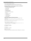
To configure an HP routing switch for PIM Sparse, perform the following tasks:
• Configure the following global parameters:
• Enable the PIM Sparse mode of multicast routing.
• If you have not already done so, enable a unicast routing protocol (RIP or OSPF).
9 - 13