


Configuring VLANs
16 - 45
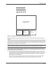
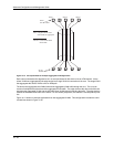
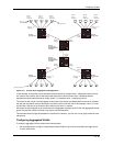
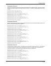
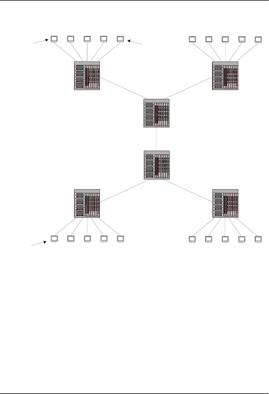
Figure 16.17 Example Super Aggregated VLAN Application
In this example, a collocation service provides private channels for multiple clients. Although the same devices
are used for all the clients, the VLANs ensure that each client receives its own Layer 2 broadcast domain,
separate from the broadcast domains of other clients. For example, client 1 cannot ping client 5.
The clients at each end of a channel appear to each other to be directly connected and thus can be on the same
sub-net and use network services that require connection to the same sub-net. In this example, client 1 is in sub-
net 192.168.1.0/24 and so is the device at the other end of client 1’s channel.
Since each VLAN configured on the core devices is an aggregate of multiple client VLANs, the aggregated VLANs
greatly increase the number of clients a core device can accommodate.
This example shows a single link between the core devices. However, you can use a trunk group to add link-level
redundancy.
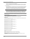
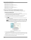
Configuring Aggregated VLANs
To configure aggregated VLANs, perform the following tasks:
• On each edge device, configure a separate port-based VLAN for each client connected to the edge device.
In each client VLAN:
Port 2/1
Tagged
Port 3/1
Untagged
Port 2/1
Tagged
Ports1/1 - 1/5
Untagged
Ports1/1 - 1/5
Untagged
Port 4/1
Tagged
Port 3/2
Untagged
Port 3/1
Untagged
Port 3/2
Untagged
Port 4/1
Tagged
Port 2/1
Tagged
Device D
TagType 9100
VLAN Aggregation
Enabled
Ports1/1 - 1/5
Untagged
Client 10
Port 1/5
VLAN 105
Client 8
Port 1/3
VLAN 103
...
...
Port 2/1
Tagged
Device A
TagType 8100
Device E
TagType 8100
Device B
TagType 8100
Device F
TagType 8100
Device C
TagType 9100
VLAN Aggregation
Enabled
192.168.1.129/24
Client 6
Port 1/1
VLAN 101
Client 5
Port 1/5
VLAN 105
Client 3
Port 1/3
VLAN 103
...
...
Client 1
Port 1/1
VLAN 101
Ports1/1 - 1/5
Untagged
209.157.2.12/24
Client 1
192.168.1.69/24