


CTI 2572 Installation and Operation Guide
90
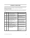
Errors in manipulating the Command Control bits may cause "multiple triggering," resulting in an
error code. Certain commands, such as those to create a connection, must be run only once.
Improperly constructed PLC logic may repeatedly trigger the command, resulting in an error code
such as 0x00A7 (duplicate connection).
8.6. Development and Debugging Tips
Manual Triggering
You can test your command blocks independently from the PLC logic that actually executes them by
manipulating the command control bits manually. First, place the PLC in program mode so that the
PLC logic will not be executing. Then you can manipulate the bits as shown below. If you are not
familiar with the 2573 PLC Command Interface, you should refer to Appendix D.
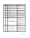
The command control bits are located in the 4th module word. For example, if you logged the
module in starting at Word 1, then the command control bits will be located in WY4. See the
WX/WY Quick Reference in Appendix C of this manual. There are 4 sets of control bits, one set for
each command slot. Any command slot can be used in any order.
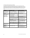
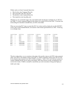
Bits 1 -4 Bits 5 - 7 Bits 8 - 11 Bits 12 -16
WY4 Command Control
Bits - Slot 1
Command Control
Bits - Slot 2
Command Control
Bits - Slot 3
Command Control
Bits - Slot 4
Hex 0-F Hex 0 - F Hex 0 - F Hex 0 - F
Within each set of four Command Control bits:
• The first bit is the Error Acknowledge,
• The second bit is the Command Mode bit,
• The third bit is the Command Trigger,
• The fourth bit Abort Trigger.
So a bit pattern of 0110 will set the command mode bit and the command trigger. Similarly, the bit
pattern 1000 will set error acknowledge. Using hexadecimal notation is a convenient way to observe
and manipulate these bits, because each hexadecimal digit represents 4 bits. Thus, bit pattern when
command trigger and command mode are high (0110) is represented by hexadecimal 6 (0+4+2+0).
Similarly, an error acknowledge bit high (1000) is represented by hexadecimal 8.
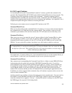
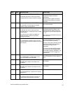
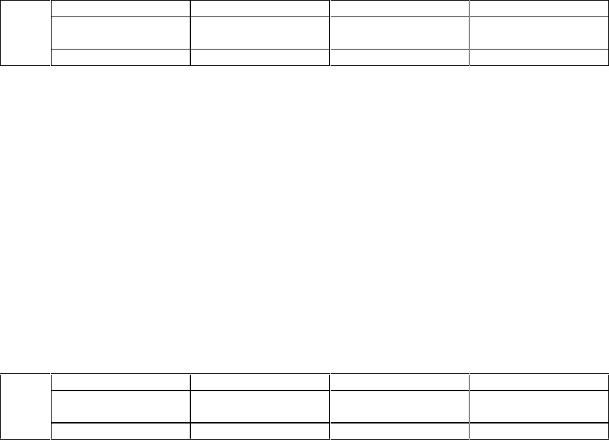
The command status bits written by the module are located at the second module word (WX2 in this
example) in a bit grouping that matches the command control word.
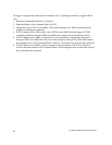
Bits 1 -4 Bits 5 - 7 Bits 8 - 11 Bits 12 -16
WX2 Command Status
Bits - Slot 1
Command Status
Bits - Slot 2
Command Status
Bits - Slot 3
Command Status
Bits - Slot 4
Hex 0-F Hex 0 - F Hex 0 - F Hex 0 - F