


CTI 2572 Installation and Operation Guide
67
data packet arrive before the PLC write has been completed, the incoming packet will overwrite the
previous data in the buffer with the new value.
PLC Command Interface
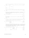
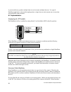
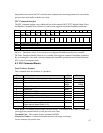
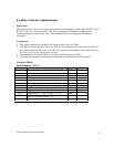
The PLC command interface uses additional bits in the standard 505-CP2572 Module Status Word
and Module Command Word structure to control scan triggered automatic DataShare production.
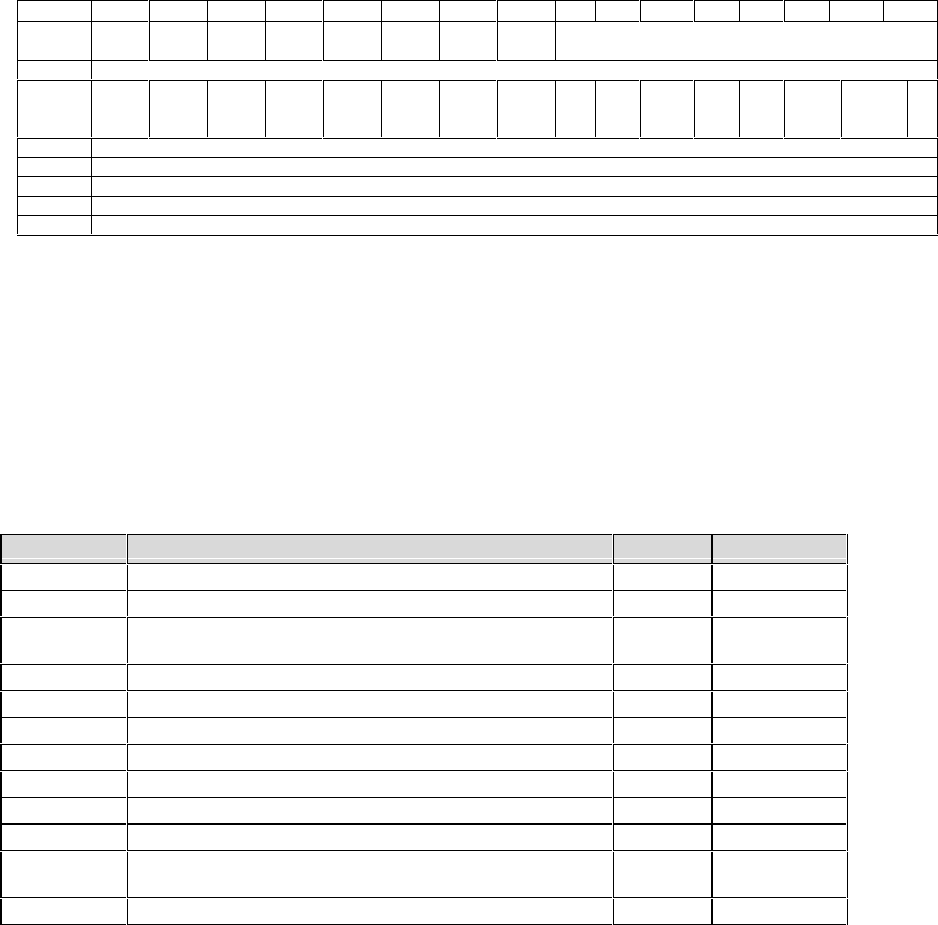
Bit 1 2 3 4 5 6 7 8 9 10 11 12 13 14 15 16
WX 1 Mod
Fail
Cfg
Req
Diag
Err
Cfg
Err
AUI
Act
DS
Act
Resv Module Timer
WX2 Standard 257x Command Status
WY3 Rst
DS
Enbl
Resv
WY4 Standard257x Command Control
WY5 Standard 257x Command Slot
WY6 Standard 257x Command Slot
WY7 Standard 257x Command Slot
Wy8 Standard 257x Command Slot
DS ACT – DataShare Active: Is set whenever scan-triggered DataShare production is enabled.
DS E
NBL- DataShare Enable: Must be set to enable scan-triggered automatic DataShare production.
By associating this value with a discrete output point, automatic production can be halted when the
PLC is placed in program mode.
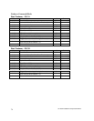
6.3. PLC Command Blocks
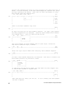
Start Producer Instance
This command starts one instance of a producer.
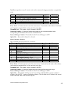
Offset Description Hex Decimal
0 Error Word 0000 0
1 Command Code (Start DataShare Producer)) 2F01 12033
2 Connection Number 4B29 –
4B30
19241-
19248
3 Protocol Manager Number 002F 47
4 Option Bits 0000 0
5 Data ID (1 - 65565)
6 MSW: Source V Memory Address
7 LSW: Source V Memory Address
8 Length of Data in Words (1 - 512)
9 Trigger Option (1 = timer, 2 = logic, 3 = scan)
10 Timer Interval (when Offset 9 = 1)
Scan Interval (when Offset 9 = 3)
11-15 Reserved, Set to 0
Error Word - will contain an error code if an error occurs. You should set this value to 0 each time
you trigger the command block to clear previous error codes.
Command Code – The number for this command is0x2F01.
Connection Number – Connection Number must be with range and unique.