


CTI 2572 Installation and Operation Guide
4
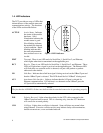
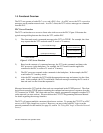
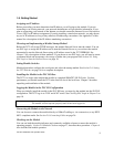
1.4. LED Indicators
The 2572 provides an array of LEDs that
inform the user of the module status and
communications activity. The functions
of the LEDs are described below:
ACTIVE Active Status. Indicates
the status of the module
hardware. Solid
illumination indicates the
module status is good.
Slow blinking indicates
the module has detected
a fault condition. Rapid
blinking indicates that
the network parameters
have not been set or are
invalid.
XMT Transmit. There is one LED each for Serial Port 1, Serial Port 2, and Ethernet,
which lights when data is transmitted on the applicable port.
RCV Receive. There is one LED each for Serial Port 1, Serial Port 2, and Ethernet. These
LEDs will light when a signal is received on the applicable port. The Ethernet LED
will flash when any network traffic is detected, not just valid packets or packets
addressed to the module.
LB Link Beat. Indicates that a link beat signal is being received on the 10BaseT port and
that the 10BaseT port is selected. This LED should be lit if 10BaseT is being used.
AUI Attachment Unit Interface. Lights to indicate that the AUI port is selected for
Ethernet communications. If a link beat is not detected on the 10BaseT port, the
AUI port will be automatically selected.
NOTE:
The fact that the AUI LED is lit does not indicate that the attached transceiver is operating properly.
POL Polarity Reversed. Lights when the polarity for the UTP cable connected to the
10BaseT port has been reversed. This is a warning only, since the 2572 hardware
will correct for reversed polarity.
COL Collision. Lights when a collision is detected. Some collisions are normal when
using Ethernet. Excessive collision activity may indicate faulty cable termination,
defective transceivers, or an overloaded network.
Figure 4. LED Indicators