


CTI 2572 Installation and Operation Guide
8
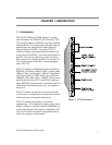
1.7. PLC Command Interface
Some 2572 functions require that you use PLC logic to control the operation of the module. The
2572 module provides a standard PLC logic interface for sending messages and processing
responses. The interface consists of two parts:
• Command Blocks - Command Blocks are blocks of contiguous V memory words used to store
module commands and associated parameters. The exact content of the Command Block will
vary with the command being issued.
• Module WX/WY Words - The 2572 module logs in as a Special Function module and is assigned
two WX words and six WY words. PLC logic uses the WY words to select the Command Block
and to trigger the command execution. The status of the module and of command execution can
be monitored via the WX words.
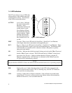
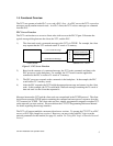
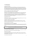
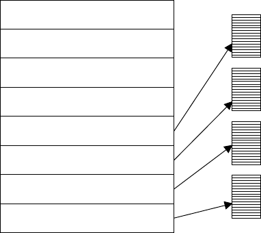
Figure 7 illustrates how the module WX/WY words and the command blocks are used together. The
2572 writes values in the WX words, the PLC writes values in the WY words. WX1 and WY3
contains bits allow the PLC to monitor and control module global status. WY4 and WX2 contain bits
that allow the PLC to trigger commands and monitor command status. The Command Slots (WY5-8)
are used to point to the starting V Memory addresses of the Command Blocks.
To use the module command interface, your PLC logic typically loads a Command Slot with the
address of the desired command block. It then sets a corresponding trigger bit in WY4 to cause the
2572 to execute the command. Your logic then monitors the condition of the command status bits in
WX2 to determine whether the command completed successfully.
Please refer to Appendix D for a complete description of the PLC Command Interface.
MODULE STATUS WORD
COMMAND STATUS WORD
MODULE CONTROL WORD
COMMAND CONTROL WORD
COMMAND SLOT 1
COMMAND SLOT 2
COMMAND SLOT 3
COMMAND SLOT 4
MODULE WX/ WY
COMMAND
BLOCKS
WX1
WX2
WY3
WY4
WY5
WY6
WY7
WY8
Figure 7. 2572 PLC Interface