


CTI 2572 Installation and Operation Guide
125
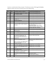
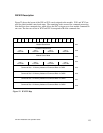
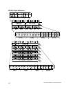
WX/WY Description
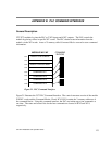
Figure 22 shows the layout of the WX and WY words assigned to the module. WX1 and WY3 are
used for global module control and status. The remaining words are used for command processing.
Note there are four command slots, which allows the PLC to trigger up to four module commands in
one scan. The four sets of bits in WX2 and WY4 correspond to the four command slots.
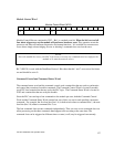
Command Status Word
1 2 3 4 5 6 7 8 9 10 11 12 13 14 15 16
Module Status Word
CMD 1
Status Bits
WX1
WX2
WY3
WY4
WY5
WY6
WY7
WY8
Command Slot 1: V Memory Address of Command Block for CMD1
Command Slot 2: V Memory Address of Command Block for CMD2
Command Slot 3: V Memory Address of Command Block for CMD3
Command Slot 4: V Memory Address of Command Block for CMD4
CMD 2
Status Bits
CMD 3
Status Bits
CMD 4
Status Bits
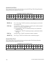
Command Control Word
CMD 1
Control Bits
CMD 2
Control Bits
CMD 3
Control Bits
CMD 4
Control Bits
Module Control Word
Figure 22. WX/WY Map