


CTI 2572 Installation and Operation Guide
5
1.5. Functional Overview
The 2572 can operate as both a PLC server and a PLC client. As a PLC server, the 2572 responds to
messages sent by another network node. As a PLC client, the 2572 initiates messages on command
from the PLC.
PLC Server Function
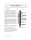
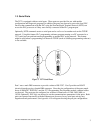
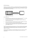
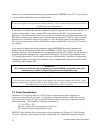
The 2572 can function as a server to clients who wish to access the PLC. Figure 5 illustrates the
typical message dialog between the client, the 2572, and the PLC.
1) The client node sends a command message to the 2572 via TCP/IP. For example, the client
may request that the 2572 read and return 25 words of V memory.
2) Based on the contents of a command message, the 2572 sends commands and data to the
PLC processor via the backplane. For example, the 2572 would issue the applicable
command to the PLC to retrieve 25 words of V memory.
3) The PLC processor responds to the command via the backplane. In the example, the PLC
would return 25 V memory words.
4) After the PLC responds, the 2572 builds the appropriate message and returns it to the client
node. In this example, the 2572 would build a network message containing the 25 words of
data and send it to the client that requested it.
Messages between the 2572 and the client node are encapsulated in the TCP/IP protocol. The client
device must create the TCP/IP packet containing the command and must process responses from the
2572 returned via TCP/IP. The client node may be a suitably programmed computer or another 2572
on the network (see next section). Please reference the CTI 2572 Programming Reference Manual
for details regarding the message interface.
The 2572 will support multiple concurrent client/server sessions. To operate the CTI 2572 as a PLC
server, no PLC logic changes are required. However, you may wish to add PLC logic to set the
network parameters for the module (see page 19, section 2.6. Using PLC Logic to Start the Network
Server).
P
L
C
2
5
7
2
1) Command Message
Server PLC / 2572
Client Node
2) PLC Command
3) PLC Response
4) Response Message
Figure 5. PLC Server Function