


CTI 2572 Installation and Operation Guide
127
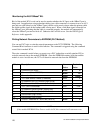
Module Control Word
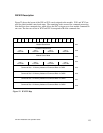
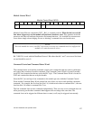
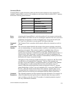
Module Control Word (WY3)
12345678910111213141516
Mod
Rst
DS
En
Module Control Bits are contained in WY3. Bit 1 is a module reset bit. When the bit is set and all
four abort triggers are set, the module will perform a hardware reset. This operation resets the
processor and starts all hardware diagnostics and startup functions. It is available for extreme error
cases where simply acknowledging an error or aborting a command does not clear the error.
NOTE:
Once the module has reset, your PLC logic must re-execute any commands used to configure the
module or to start the network server.
Bit 7 (DS EN) is used with the DataShare Protocol. Bits other than bit 1 and 7 are reserved for future
use and should be set to 0.
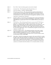
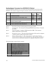
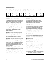
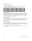
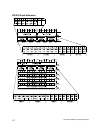
Command Control and Command Status Words
The command status word and the command control word contains bits that are used to synchronize
and control the execution of module commands. The Command Control Word is located in module
word WY4 and contains bits that are set by the PLC logic. The Command Status Word is located in
WX2 and contains bits that are set by the module.
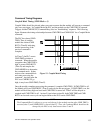
Since the PLC can send up to four commands to the module per scan, both the Command Control
Word and the Command Status Word contain four sets of bits, one set for each possible concurrent
command. For example, the first four bits (bits 1-4) in both words relate to command Slot 1, the next
four bits (bits 5-8) relate to command Slot 2, etc.
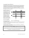
The four command slots execute commands independently. Thus, an error on one command does not
affect processing on the other commands than happen to be executing at the same time. The
command slots can be triggered at different times or some (or all) may be triggered concurrently.