


CTI 2572 Installation and Operation Guide
136
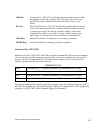
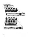
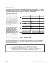
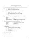
PLC Error Timing
A PLC error occurs when the module cannot read a valid Command Block from the PLC V memory
or it cannot write back to this location. The following diagram illustrates timing for the PLC ERR bit.
Note that the shaded area indicates a "don’t care" condition for the particular bit.
At time A, the module has set
CMD BUSY and attempts to
retrieve the command block
from V memory. At time B, the
module determines it cannot
retrieve a valid command block
and asserts the CMD ERR and
the PLC ERR bit. Since a valid
command cannot be retrieved,
the module halts processing of
this command.
At time C the module samples
the ERROR ACK bit and
determines that it is asserted,
indicating that the PLC has
acknowledged the error. Some
time later the module clears the
CMD ERR and PLC ERR bits
(Time D) and the CMD BUSY
bit (Time E). The error bits will
always be cleared prior to or at
the same time as CMD BUSY.
Note that, in this example, no error code is written to the command block. Since a Command Block
could not be read, the module does not attempt to write an error code into the V memory location
indicated in the command slot.
NOTE:
When the PLC ERR bit is set, it is almost always the result of:
1) an invalid address in the Command Slot (WY5, WY6, WY7, or WY8) or
2) a command block connection number that does not have hex 4B in the high byte
If the PLC ERR bit is on, you should check your PLC logic carefully!
Figure 26. PLC Error Timing