


CTI 2572 Installation and Operation Guide
129
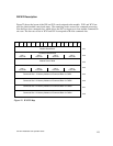
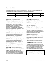
CMD Err
Command Error. The 2572 sets this bit when it encounters an error while
attempting to execute the command. The 2572 will write an error code
into Offset 0 of the command block unless PLC E
RR is also set (see
below).
PLC Err
PLC Read/Write Error. The 2572 sets this bit to indicate that it could not
read a valid command block from V memory. Therefore, there is no place
to write an error word. This may be caused by loading a value in the
Command Slot which is not a valid V memory location (such as 0) or
which points to V memory that does not contain a Command Block.
CMD Busy
Indicates the module is in the process of executing a command.
ABORT Busy
Indicates the module is attempting to abort a command.
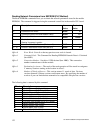
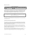
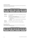
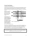
Command Slots (WY5-WY8)
Module words WY5, WY6, WY7, and WY8 are called Command Slots. There are four command
slots, one for each possible concurrent command. The value in the command slot points to the V
memory address of a command block as illustrated below. Addresses of 0 or less are invalid.
Addresses greater than 64k cannot be referenced.
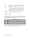
COMMAND SLOTS
WY5 Command Slot 1: V Memory Address of Command Block for CMD1
WY6 Command Slot 2: V Memory Address of Command Block for CMD2
WY7 Command Slot 3: V Memory Address of Command Block for CMD3
WY8 Command Slot 4: V Memory Address of Command Block for CMD4
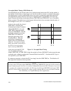
Note that the command slots match up with the command control and command status bits in WY4
and WX2. For example, the command block whose address in Command Slot 1 will be triggered by
setting bit 3 in WY4 (Bit 3 is the Command Trigger for Command 1).