


CTI 2572 Installation and Operation Guide
24
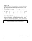
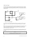
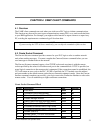
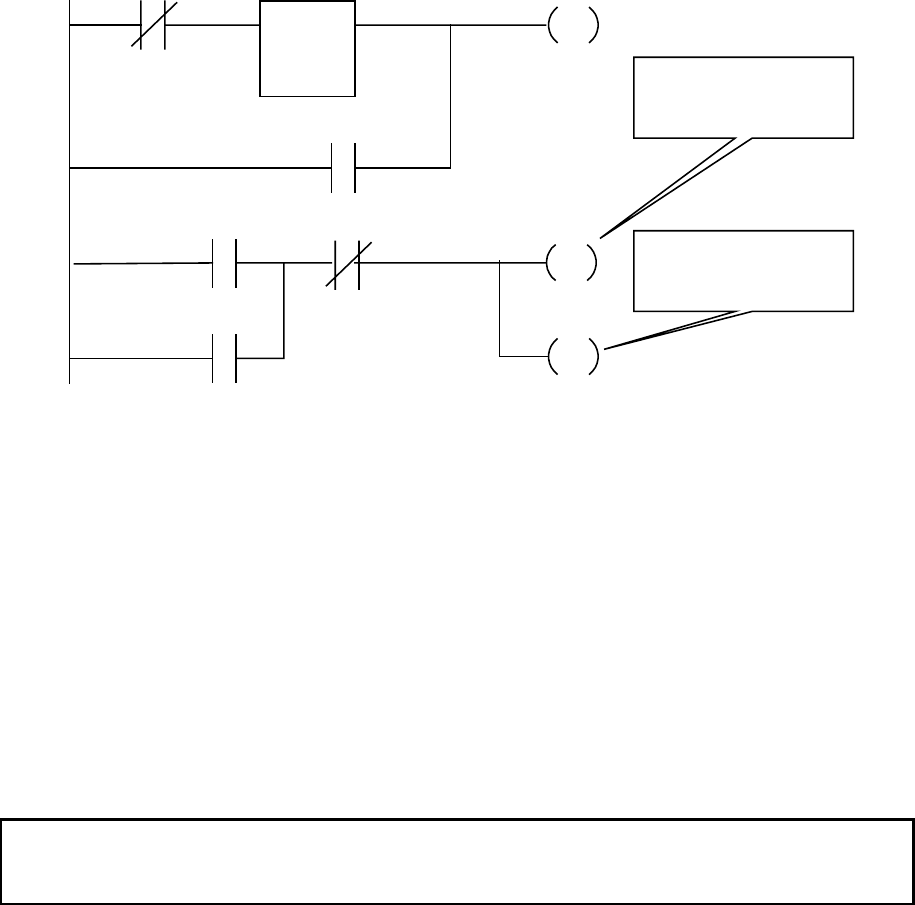
Ladder Logic Example
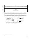
The following diagram illustrates the ladder logic that executes the Start Network Server command
block. This example assumes that the command block is located in V memory starting at V500 and
that command slot 1 is used for the command. See the CTI 2572 PLC Command Interface Reference
Manual for details.
Rung 1 loads the location of the Command Block (V500) into Command Slot 1 (WY5). Once the
control relay is on, it seals off the command. The load command will be bypassed on subsequent
scans.
Rung 2 sets the C
OMMAND TRIGGER (WY4.3) and COMMAND MODE (WY4.2) when the NET CFG bit
(WX1.3) is on and the C
OMMAND BUSY bit (WX2.3) is off. When the logic sees the 2572 raise
C
OMMAND BUSY (WX2.3), it lowers the COMMAND MODE (WX4.2) and COMMAND TRIGGER
(WX4.3), completing the coupled mode cycle.
The N
ET CFG bit will be raised by the 2572 at any time the network configuration parameters are not
set. Therefore this logic will re-execute the Start Network Server command, if the 2572 is reset for
any reason.
NOTE:
Do not use retentive relays in this logic. Proper operation of this logic depends on the control relay
transitioning from off to on when power is cycled.
LDC
WY5
500
C100
C100
C100
WY4.2
WX2.3
WY4.3
WX1.3
WY4.3
Set the command to
Coupled Mode
Sets the Command
Trigger
Figure 13. PLC Logic Example