


CTI 2572 Installation and Operation Guide
12
allows you to load the information directly from data stored in EEPROM on the 2572. You will need
to decide which method best suits your requirements.
NOTE:
Unless your application requirements dictate otherwise, CTI recommends that you allow the PLC to
establish the network parameters.
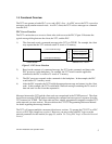
If you choose to establish the network parameters using PLC logic, the 2572 will wait for the PLC to
initiate network startup. Using a special 2572 startup command, the PLC can set the network
parameters. When the module is reset for any reason (for example, during module replacement), the
PLC must restart the server software and re-load the network parameters. The PLC logic to perform
this function is described in Section 2.6 on page 19. Since the IP information is reloaded from the
PLC and is not stored in the module, the IP address remains with the PLC, even if the 2572 modules
are swapped.
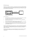
If you choose to obtain the network parameters from the EEPROM, the module automatically
initiates network startup based on the values in EEPROM. No PLC logic is required to set the
network parameters. Since the IP address is not associated with the PLC program, you can download
a common program to multiple PLCs using the TCP/IP network. However, if you arbitrarily swap
2572 modules between PLCs, the IP address will move with the module. The effect of inadvertently
swapping IP addresses can cause major problems, since communications directed at one PLC would
actually be going to another PLC.
WARNING:
If you choose to obtain the network parameters from EEPROM, you should ensure your
maintenance procedures safeguard against inadvertent module swaps.
NOTE:
You will need to specify the IP address of the module, the logical port number for the PLC server
function, subnet mask, and the IP address of the default router. You may need to obtain some of this
information from your network administrator before you begin.
2.2. Power Requirements
The Model 2572 requires 6 watts of +5 VDC power, not including any power supplied to a
transceiver connected to the AUI port. If your media configuration requires a transceiver and you
wish to power it from the AUI port, you should include the transceiver power requirement in your
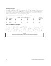
power calculations. The formula for slot power calculation is:
P = 6 + (TP x 1.15)
where P = total power slot requirement in watts and
TP = transceiver power requirement in watts.
IEEE 802.3 specifications allow a transceiver to draw a maximum of 500 ma at 12 VDC from the
AUI port. In practice, many transceivers draw considerably less. Should the total power required