


CTI 2572 Installation and Operation Guide
44
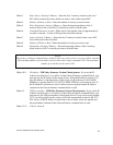
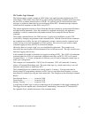
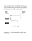
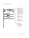
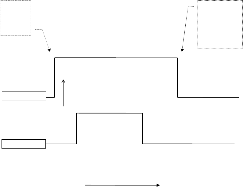
Note the function of C14 and C15. They are used to detect the fact that a 2572 command cycle has
completed. Refer to the timing diagram below. The 2572 will raise the Command Busy it after the
PLC logic sets the command trigger. If there is no error, the 2572 will lower command busy after the
PLC lowers the command trigger and the 2572 module has successfully completed the command. If
there is an error, the 2572 will raise the error bit. In this case, it will not lower the command busy bit
until the PLC sets the error acknowledge bit. When the command busy bit is lowered, the command
cycle is complete and the 2572 can accept another command in the command slot.
Please refer to Appendix D for detailed information regarding the timing of the trigger, command
busy and command error bits. C14 is used to latch the beginning of a command cycle. When the
command busy bit is lowered after C14 has been set, C15 is set. When C15 is set, the command
cycle has been completed.
Command Busy Bit
Time
C14 is set
here when
Command
Busy bit
comes on
On
C15 is set here
when Command
Busy bit goes off,
after C14 is on,
indicating a
complete
command cycle
Command Error Bit