


CTI 2572 Installation and Operation Guide
91
Within each set of four Command Status bits:
• The first bit is the Command Error bit,
• The second bit is the PLC Error bit,
• The third bit is the Command Busy bit,
• The fourth bit is the Abort Busy bit.
Therefore, to set a command trigger only (uncoupled mode) for the first command slot, set WY4 to
hex 2000. To set the command trigger for the second slot, set the WY4 to hex 0200. To set the error
acknowledge for the third Command Slot, set WY4 to hex 0080.
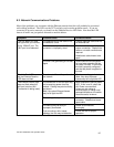
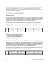
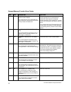
When you are using PLC logic to control the PLC, it is often useful to display the module WX/WY
words, parts of the command blocks, and sections of the format specifications as a chart. Following
is an example chart.
LOCATION STATUS LOCATION STATUS LOCATION STATUS
WX1 = HEX V100 = HEX V300 = HEX
WX2 = HEX V101 = INTEGER V301 = INTEGER
WY3 = HEX V102 = INTEGER V302 = INTEGER
WY4 = HEX V103 = INTEGER V303 = INTEGER
WY5 = INTEGER V104 = INTEGER V304 = INTEGER
WY6 = INTEGER
WY7 = INTEGER V120 = HEX V2000 = INTEGER
WY8 = INTEGER V121 = INTEGER V2001 = INTEGER
V122 = INTEGER V2002 = INTEGER
V123 = INTEGER V2003 = INTEGER
V124 = INTEGER V2004 = INTEGER
V2005 = INTEGER
The above chart allows you to examine at the value of the module status word (WX1), the command
status word (WX2), the module control word (WY3), and the command control word (WY4) in hex.
It also displays the command slots (WY5-WY8) as integers. V100, V120, and V140 are assumed to
contain command blocks you are using; this display shows the first four words, including the error
word in hex format. V2000 is assumed to contain data you wish to monitor. Change the display to
match your setup.