


CTI 2572 Installation and Operation Guide
48
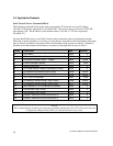
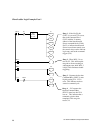
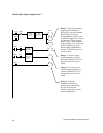
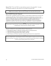
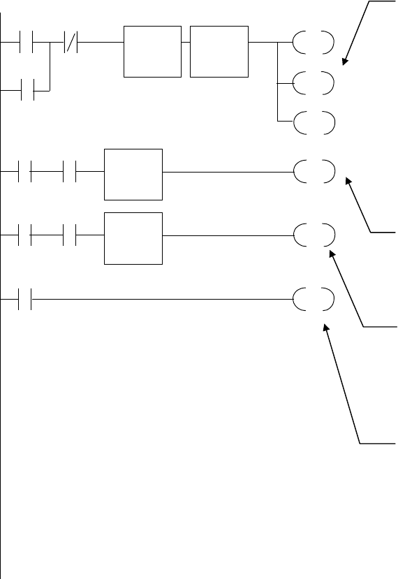
Client Ladder Logic Example: Part 3
MOVW
A: V120
B: V400
N = 1
C12
WX2.1 C18
MOVW
A: V140
B: V401
N = 1
C13
WX2.1 C18
C19
WY4.3
WX2.3
WY4.2
WY4.3
LDC
A: V140
N = 0
LDC
A: V120
N = 0
C19
RST
WX2.1
WY4.1
Rung 8 - This is the command
trigger for Command Slot 1.
When C19 is set and Command
Busy(WX2.3) is low, the
Command Mode (WY4.2) and
Command Trigger (WY.4.3) bits
are turned on . These are held
high by WY4.3 until command
busy goes high. C19 is reset and
must be explicitly set again
before another command will
execute. The LDC boxes clear
the error words.
Rung 9 - If an error occurs
while attempting to Create a
Network Connection (C12 on),
this stores the error word in
V400.
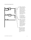
Rung 10
- If an error occurs
while attempting the memory
transfer command (C13 on),
this stores the error word in
V400.
Rung 11
- When the
command error bit is on,
raise the error acknowledge
bit. This will cause the
module to clear the error and
lower command busy.