


CTI 2572 Installation and Operation Guide
43
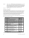
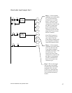
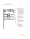
PLC Ladder Logic Example
The following pages contain a sample of a PLC ladder logic application that implements the 2572
Client Mode. Client Mode allows the PLC to send a message containing commands and/or data from
the local PLC to another network node via TCP/IP. It is typically used to send unsolicited alarm
messages or production data based on an event detected by the PLC. Potential message recipients
include network computers or other PLCs using a 2572.
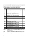
This sample application executes a S
TART NETWORK SERVER command to set the module IP address
and other network parameters. Once this command is completed successfully, the application
establishes a socket to communicate with another network device using the C
REATE SOCKET
command.
The example command block is for UDP; however, it can be easily modified to create a TCP
connection by changing one parameter in the command block. Once the C
REATE SOCKET command
has completed successfully, the logic will continuously execute a memory transfer command (read
remote) as long as an event represented by C100 is present. Error recovery logic includes simple
command logging and retry and TCP re-connection attempts.
Obviously, there is no single “right” way to accomplish this application. This example is not
necessarily the most elegant or efficient alternative, but it is known to work. The logic includes error
detection, logging, and recovery.
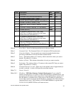
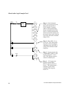
In this example, the module is assumed to be logged in starting at WX1. Thus, WX2 will contain the
command status bits, WY4 will contain the command control bits, and WY5 - WY 8 will contain
Command Slots 1 - 4. If your configuration is different, you will need to change the sample logic to
match your configuration.
This example uses Command Slot 1 (WY5) for all commands. WY5 will contain the V memory
address of Command Block being used. The state of the logic (e.g. which control relay is set) will
determine which address is loaded into WY5.
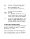
The Command Blocks are assumed to be already stored in V memory. You may enter them in
directly using PLC programming software, use PLC logic to copy them from K memory, or create
them directly in ladder logic using the load constant box. The example uses the following Command
Blocks:
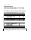
Start Network Server ............... located at V100
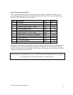
Create Socket .......................... located at V120
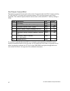
Memory Transfer ..................... located at V140.
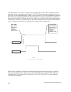
A single rung of ladder logic is used to set the trigger for all commands for the single command slot.
The trigger uses the coupled mode, which enforces “handshaking” between the 2572 and the PLC.
See Appendix D for a detailed discussion of the command mode.