


CTI 2572 Installation and Operation Guide
73
PLC Logic
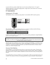
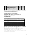
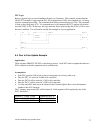
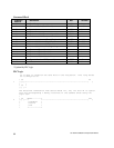
Below is typical logic to start a DataShare Producer or Consumer. This example assumes that the
505-CP2572 module is logged into the PLC I/O configuration at WX1 and command slot 1 is being
used for command processing. The command block being executed begins at V100. The command
is fired on the rising edge of X1. If a command error is encountered, the 2572 module will turn the
error bit (WX2.1) ON. In that case, the logic turns the Error Acknowledge bit (WY4.1) ON to clear
the error condition. You will need to modify this example to fit your application.
! X1 1 LDC-----------+ WX2.3 WY4.2
1 [-] [---:O:---! !-*-]/[-------------------------------*-( )
! ! A:WY5 ! ! !
! ! N=100 ! ! ! WY4.3
! ! ! ! +-( )
! +-------------+ !
!WY4.3 !
[-] [-------------------------+
!
!WX2.1 WY4.1
18 [-] [---------------------------------------------------------------( )
!
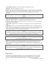
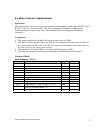
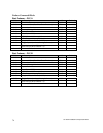
6.5. Peer to Peer Update Example
Application
There are three SIMATIC 505 PLCs controlling a process. Each PLC needs to update the other two
PLCs with data so that the operation can be synchronized.
Assumptions
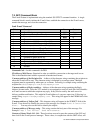
• Each PLC produces 100 words of data at a requested rate of every other scan.
• Data for PLC A is stored at V1000 in all controllers
• Data for PLC B will be stored at V1100 in all controllers.
• Data for PLC C will be stored at V1200 in all controllers.
• To allow each PLC data area to be identical, the Consumer Option bit to write the Sequence
number to the PLC is not set.
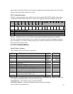
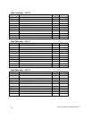
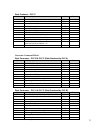
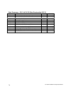
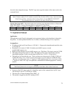
The V memory map in each PLC will be identical. Each segment will be updated by one of the
PLCs. See below.
Segment 1: V1000- V1099 Updated by PLC A
Segment 2: V1100- V1199 Updated by PLC B
Segment 3: V1200- V1299 Updated by PLC C