


CTI 2572 Installation and Operation Guide
133
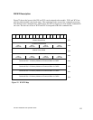
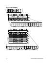
Command Timing Diagrams
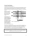
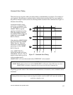
Coupled Mode Timing (CMD Mode = 1)
Coupled Mode should be selected when you want to ensure that the module will execute a command
only once per trigger. In Coupled Mode the PLC and the module use the CMD TRIG (Command
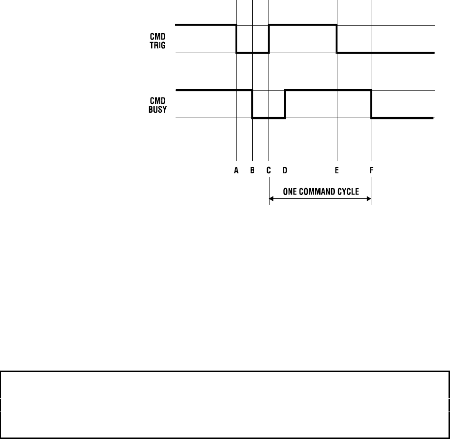
Trigger) and the CMD BUSY (Command Busy) bits in a "handshaking" sequence. The following
figure illustrates the timing relationships between CMD TRIG and CMD BUSY for a Coupled Mode
command.
The PLC has cleared CMD
TRIG (Time A) and the
module has cleared CMD
BUSY (Time B) indicating
that the processing of the
previous command is
complete.
At Time C, the PLC asserts
CMD TRIG to initiate a
command. When the module
recognizes that CMD TRIG is
high, it asserts CMD BUSY
(Time D) and samples the
CMD MODE bit to determine
the command mode. It then
retrieves the command block
and starts processing the
command. Any time after the
PLC sees CMD BUSY go
high, it may lower CMD TRIG (Time E).
Once the module completes processing the command, it samples CMD TRIG. If CMD TRIG is off,
the Module will lower CMD BUSY (Time F) and wait for the next trigger. If CMD TRIG is on, the
module will hold busy high and wait until CMD TRIG is turned off. Time F will be delayed as
required until CMD TRIG is off. At time F (equivalent to time B), both CMD TRIG and CMD
BUSY are low and a new cycle can begin whenever the PLC asserts CMD TRIG.
NOTE:
The Command Block is subject to access and change by the module anytime after CMD TRIG is
asserted (time C) until CMD BUSY is cleared (time F). Thus, the Command Block should not be
changed by the PLC at any time between time C and F.
Figure 23. Coupled Mode Timing