


CTI 2572 Installation and Operation Guide
130
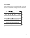
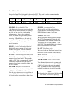
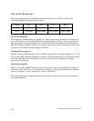
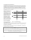
WX2 and WY4 Relationships
The following illustrates the relationship between the first four bits in WX2 and WY4. This
relationship applies to the other three sets of bits.
WordBit 1Bit 2Bit 3Bit 4
WX2 CMD Err PLC Err CMD Busy Abort Busy
WY4 ERR Ack CMD Mode CMD Trigger Abort Trigger
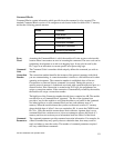
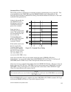
Error Processing Bits
The module will set CMD ERR any time an error occurs in processing a command. The module will
also set PLC E
RR if a valid Command Block cannot be read from V memory. After setting the error
bits, the module will halt processing on this command. The PLC acknowledges the error by setting
ERR A
CK. When the module sees ERR ACK go high, it aborts the command, clears the error bits, and
is ready to accept another command trigger for this slot.
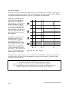
Command Processing bits
The PLC sets the CMD MODE bit to select whether Coupled Mode or Uncoupled Mode is used. The
PLC sets the CMD T
RIGGER to initiate the command. When the module begins command processing,
it sets the CMD B
USY bit. The CMD BUSY bit will remain on until the module has competed
processing the command.
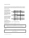
Abort Processing Bits
The PLC can set the ABORT TRIGGER to request the module to abort a command that is in process.
When the module starts the process of aborting a command, it raises the A
BORT BUSY bit. When the
process is complete, it lowers A
BORT BUSY (and also CMD BUSY).
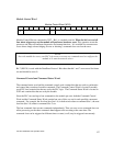
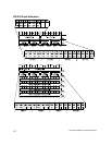
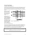
The timing diagrams in this appendix describe the interaction of the various Command Control and
Command Status bits.