


CTI 2572 Installation and Operation Guide
126
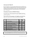
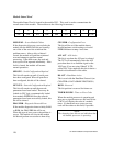
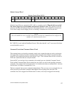
Module Status Word
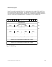
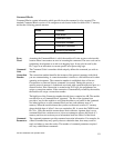
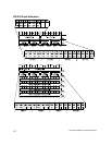
The module Status Word is located in the module WY1. This word is used to communicate the
overall status of the module. The module uses the following bit structure:
123456789 - 15
MOD
FAIL
SER
CFG
NET
CFG
DIAG
ERR
CFG
ERR
AUI
ACT
DS
ACT
RSVD Timer
E Code
MOD FAIL - Severe Module Failure
If the diagnostics discovers a severe fault, the
module sets the MOD FAIL bit and (usually)
one of the of the error bits to indicate the
problem source. After a delay of about 1
second, the module will perform an internal
reset and attempt to perform normal
processing. If the fault recurs, the wait and
reset cycle will be repeated indefinitely. If the
fault is cleared, the module will resume
normal operations.
SER CFG - Serial Configuration Required
This bit will remain set until all serial ports
have been configured. When all ports have
been configured, this bit will be cleared.
NET CFG - Network Configuration Required
This bit will remain set until the network
parameters have been loaded. These may be
loaded via PLC logic or automatically loaded
from module EEPROM. Once the network
parameters have been successfully loaded, this
bit will be cleared.
DIAG ERR - Diagnostic Detected Error
If the module diagnostics detect a faulty RAM
or ROM, the DIAG ERR bit will be set.
When this type of error occurs, the problem is
severe. The module will also set the module
fail bit and perform a reset after a short delay.
CFG ERR - Configuration Error
This bit will be set if the module detects
invalid hardware switch settings or invalid
EEPROM data at startup / reset time.
AUI ACT - AUI Active
This bit is set when the AUI port is selected.
The 2572 will automatically select the AUI
port when there is no link beat signal on the
10bT port. If you are using 10baseT (UTP)
cables, PLC logic might use this bit to detect a
break or disconnection of the cable.
DS ACT – DataShare Active
This is used with the DataShare Protocol (see
CHAPTER 6. DATASHARE PROTOCOL)
RSVD - Reserved
This bit position is reserved for future use.
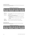
TIMER/ ECODE - Timer or Error Code
When the module processor is operating and
there are no significant errors, the lower 8 bits
of WX1 will display the value of a module
timer. If a hardware error occurs, an error
code will be written to this field, if possible.
NOTE:
The changing timer bits are an indication that
the module processor is operating.