


CTI 2572 Installation and Operation Guide
46
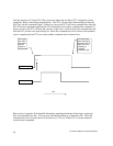
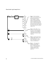
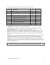
Client Ladder Logic Example: Part 1
WX1.3 C2 C1
SET
LDC
A: WY5
N = 100
C12
RST
C13
RST
C14
RST
C15
RST
C19
SET
C2WX1.3
WX2.3
C14
SET
C15
RST
C14 C15
SET
WX2.3
C14
RST
Rung 1 - If the Net Cfg bit
(WX1.3) is on and C2 is not on,
then load Command Slot 1
(WY5) with the V memory
address of the Start Network
Server command block (V100).
Set C1 to indicate that Network
Server has not been started, reset
the control relays used to indicate
logic state, and set the command
trigger (C19).
Rung 2 - When WX1.3 is on,
turn on C2. This will keep the
rung above from executing on
subsequent scans while WX1.3
is high. This eliminates double
triggering.
Rung 3 - Captures the fact that
Command Busy (WX2.3) went
high by setting C14. C15 is
reset. This indicates we have
started a command cycle.
Rung 4- - C15 captures the
fact that Command Busy
(WX2.3) went low after C14
was set. This indicates that a
command cycle has been
completed. This rung also
resets C14.