


CTI 2572 Installation and Operation Guide
123
APPENDIX D. PLC COMMAND INTERFACE
General Description
CTI 2572 modules log into the PLC as 2 WX inputs and 6 WY outputs. The PLC controls the
module by placing values in specific WY words. The PLC obtains status information from the
module via the WX words. Areas of V memory called Command Blocks are used to store command
information.
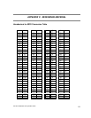
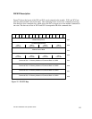
Figure 21 illustrates the 2572 PLC Command Interface. The control structures consist of the module
WX/WY words and the Command Blocks. Words WY5-WY8 contain the V memory addresses of
the command blocks. Using this command interface, the PLC can initiate up to four commands at
one time. The status and control bits for the four commands are located in WX2 and WY4,
respectively.
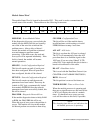
MODULE STATUS WORD
COMMAND STATUS WORD
MODULE CONTROL WORD
COMMAND CONTROL WORD
COMMAND SLOT 1
COMMAND SLOT 2
COMMAND SLOT 3
COMMAND SLOT 4
MODULE WX/ WY
COMMAND
BLOCKS
WX1
WX2
WY3
WY4
WY5
WY6
WY7
WY8
Figure 21. PLC Command Interface