


Platform Management Intel® Server Board SE7520JR2
Revision 1.0
C78844-002
122
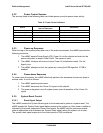
5.2.1 Server Management I
2
C Buses
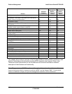
The table below describes the server management I
2
C bus assignments and lists the devices
that are connected to the indicated bus. The column labeled “I
2
C Bus ID” represents the
physical I
2
C bus connected to the mBMC. Only the Peripheral SMBus is available for use with
the Write-Read I
2
C IPMI command.
Table 46: Server Management I
2
C Bus ID Assignments
I
2
C Bus ID Bus Name Devices Connected
1 Host SMBus SMBus, PCI slots, ICH5, mBMC, DIMM FRU
2 Peripheral SMBus
SMLink, ICH5, mBMC, SIO 3, LM93, control panel, PDB,
Baseboard Temp Sensor, BMC FRU
4 Private Bus 4 – PB4 Network Interface Chipset
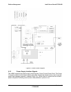
5.2.2 Power Control Interfaces
The mBMC is placed between the power button and the chipset so it can implement the Secure
Mode feature of disabling the power button, and add additional power control sources to the
system. In addition to the mandatory chassis controls, such as power–down and power-up, the
mBMC supports power cycle and pulse diagnostic interrupt.
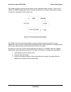
The mBMC Chassis Control command supports the following power behavior.
• Power down (0h – Chassis Control command): This option asserts a 4s override to the
chipset
• Soft Shutdown (5h – Chassis Control command): This option generates a 200ms pulse of
the chipset power button
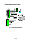
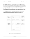
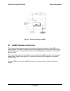
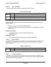
5.2.3 External Interface to the mBMC
The following figure shows the data/control flow to and within the functional modules of the
mBMC. External interfaces, namely the host system, Lan-On-Motherboard (LOM), and
peripherals interact with the mBMC through the corresponding interface modules.
Power supply control functions and control panel control functions are built into the mBMC. The
mBMC communicates with the internal modules using its private SMBus. External devices and
sensors interact with the mBMC using the peripheral SMBus. LOM communicates through the
LOM SMBus.