


Intel® Server Board SE7520JR2 Functional Architecture
Revision 1.0
C78844-002
67
3.4.10.2 Serial Ports
The baseboard provides two serial ports: an external RJ45 Serial B port, and an internal DH10
Serial A header. The following sub-sections provide details on the use of the serial ports.
3.4.10.2.1 Serial Port A
Serial A is an optional port, accessed through a 9-pin internal DH-10 header. A standard DH10
to DB9 cable is used to direct Serial A out the back of a given chassis. The Serial A interface
follows the standard RS232 pin-out as defined in the following table.
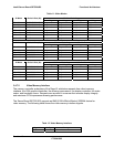
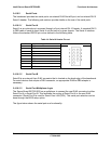
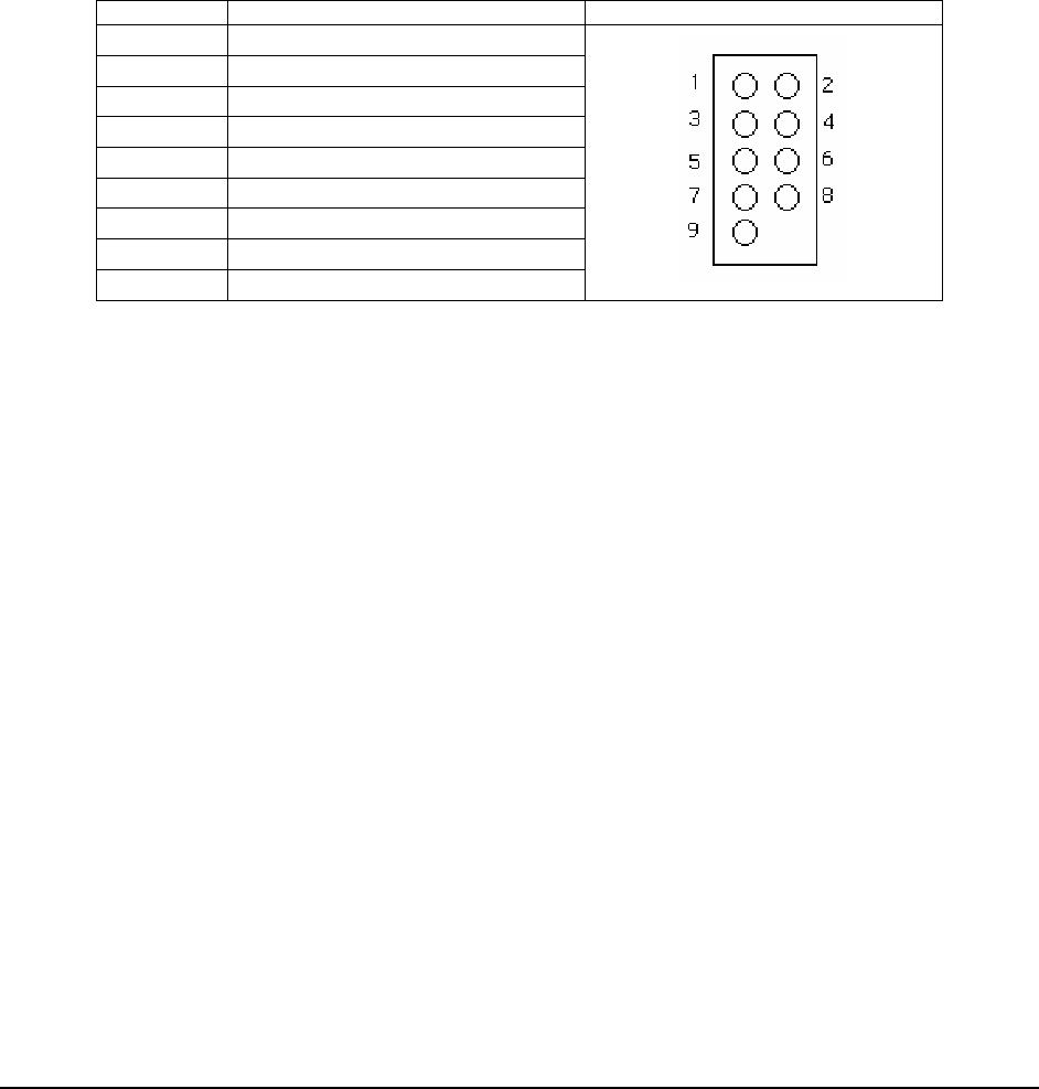
Table 14: Serial A Header Pin-out
Pin Signal Name Serial Port A Header Pin-out
1 DCD
2 DSR
3 RX
4 RTS
5 TX
6 CTS
7 DTR
8 RI
9 GND
3.4.10.2.2 Serial Port B
Serial B is an external 8-pin RJ45 connector that is located on the back edge of the baseboard.
For serial devices that require a DB-9 connector, an appropriate RJ45-to-DB9 adapter is
necessary.
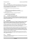
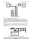
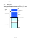
3.4.10.2.3 Serial Port Multiplexer Logic
The Server Board SE7520JR2 has a multiplexer to connect the rear RJ45 connector to either
Serial Port A or Serial Port B. This facilitates the routing of Serial Port A to the rear RJ45
connector if Serial Port B is used for Serial Over LAN (SOL). This serial port selection can be
done through the BIOS setup option.
The figure below shows the serial port mux functionality.