


Error Reporting and Handling Intel® Server Board SE7520JR2
Revision 1.0
C78844-002
172
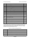
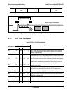
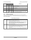
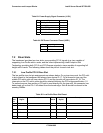
Diagnostic LED Decoder
G=Green, R=Red, A=Amber
Checkpoint
MSB LSB
Description
FA A R A R
Check the validity of the recovery file configuration to the current
configuration of the flash part.
FB A R A A
Make flash write enabled through chipset and OEM specific method.
Detect proper flash part. Verify that the found flash part size equals
the recovery file size.
F4 R A R R The recovery file size does not equal the found flash part size.
FC A A R R Erase the flash part.
FD A A R A Program the flash part.
FF A A A A
The flash has been updated successfully. Make flash write disabled.
Disable ATAPI hardware. Restore CPUID value back into register.
Give control to F000 ROM at F000:FFF0h.
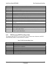
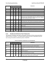
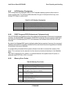
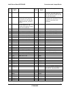
6.5.6 DIM Code Checkpoints
The Device Initialization Manager (DIM) module gets control at various times during BIOS
POST to initialize different Buses. The following table describes the main checkpoints where the
DIM module is accessed:
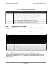
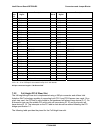
Table 78: DIM Code Checkpoints
Checkpoint Description
2A Initialize different buses and perform the following functions:
Reset, Detect, and Disable (function 0). Function 0 disables all device nodes, PCI devices,
and PnP ISA cards. It also assigns PCI bus numbers.
Static Device Initialization (function 1). Function 1 initializes all static devices that include
manual configured onboard peripherals, memory and I/O decode windows in PCI-PCI
bridges, and noncompliant PCI devices. Static resources are also reserved.
Boot Output Device Initialization (function 2). Function 2 searches for and initializes any
PnP, PCI, or AGP video devices.
38 Initialize different buses and perform the following functions:
Boot Input Device Initialization (function 3). Function 3 searches for and configures PCI
input devices and detects if system has standard keyboard controller.
IPL Device Initialization (function 4). Function 4 searches for and configures all PnP and
PCI boot devices.
General Device Initialization (function 5). Function 5 configures all onboard peripherals that
are set to an automatic configuration and configures all remaining PnP and PCI devices.