


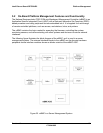

Intel® Server Board SE7520JR2 Platform Management
Revision 1.0
C78844-002
129
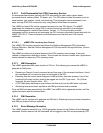
5.3.5.4.2 Fault / Status LED
The following table shows mapping of sensors/faults to the LED state.
Table 50: Fault / Status LED
Color Condition When
Solid System ready
Green
Blink System ready, but degraded: CPU disabled
Solid Critical failure: critical fan, voltage, or temperature state
Amber
Blink Non-critical failure: non-critical fan, voltage, or temperature state
Off Solid System not ready: POST error / NMI event / CPU or terminator missing
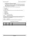
Critical Condition - Any critical or non-recoverable threshold crossing associated with the
following events:
• Temperature, voltage, or fan critical threshold crossing
• Critical Event Logging errors, including System Memory Uncorrectable ECC errors and
FSB Bus errors,.
Non-Critical Condition
• Temperature, voltage, or fan non-critical threshold crossing
• Chassis intrusion
Degraded Condition
• One or more processors are disabled by Fault Resilient Boot (FRB)
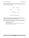
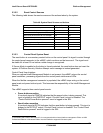
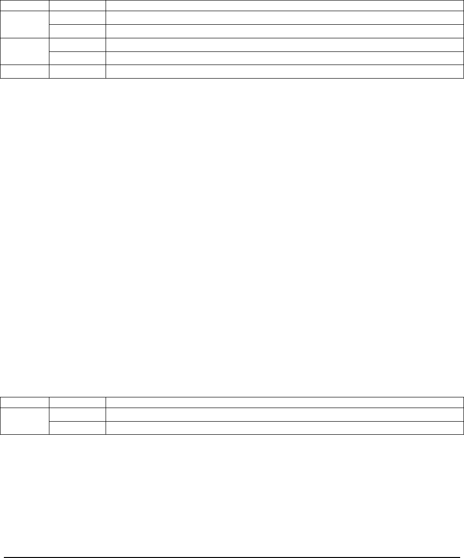
5.3.5.4.3 Chassis ID LED
The Chassis ID LED provides a visual indication of a system being serviced. The state of the
Chassis ID LED is toggled by the chassis ID button or it can be controlled by the Chassis
Identify command.
Table 51: Chassis ID LED
Color Condition When
Off Ok
Blue
Blink Identify button pressed or Chassis Identify command executed
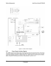
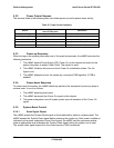
5.3.5.5 Control Panel Inputs
The mBMC monitors the control panel switches and other chassis signals. The control panel
input buttons are momentary contact switches, which are de-bounced by the mBMC processor
firmware. The de-bounce time is 25 ms.