


Intel® Server Board SE7520JR2 Connectors and Jumper Blocks
Revision 1.0
C78844-002
197
3 RXD (receive data)
4 RTS (request to send)
5 TXD (Transmit data)
6 CTS (clear to send)
7 DTR (Data terminal ready)
8 RI (Ring Indicate)
9 Ground
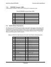
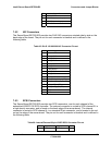
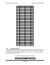
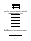
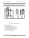
7.5.8 Keyboard and Mouse Connector
Two stacked PS/2 ports are provided to support both a keyboard and a mouse. Either PS/2 port
can support a mouse or keyboard. The following table details the pin-out of the PS/2 connector.
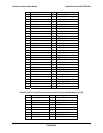
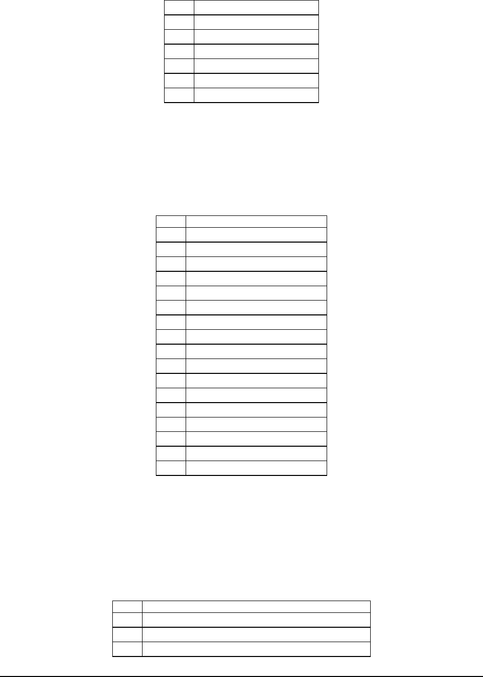
Table 102: Stacked PS/2 Keyboard and Mouse Port Pin-out
Pin Signal Name
1 Keyboard Data
2 Test point – keyboard
3 GND
4 Keyboard / mouse power
5 Keyboard Clock
6 Test point – keyboard / mouse
7 Mouse Data
8 Test point – keyboard / mouse
9 GND
10 Keyboard / mouse power
11 Mouse Clock
12 Test point – keyboard / mouse
13 GND
14 GND
15 GND
16 GND
17 GND
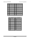
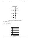
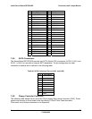
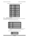
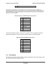
7.5.9 USB Connector
The following table details the pin-out of the external USB connectors found on the back edge of
the server board.
Table 103: External USB Connector Pin-out
Pin Signal Name
1 USB_PWR
2 DATAL0 (Differential data line paired with DATAH0)
3 DATAH0 (Differential data line paired with DATAL0)