


Error Reporting and Handling Intel® Server Board SE7520JR2
Revision 1.0
C78844-002
168
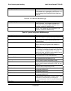
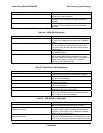
Result Amber Green Red Off
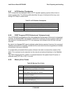
MSB LSB
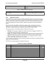
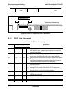
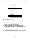
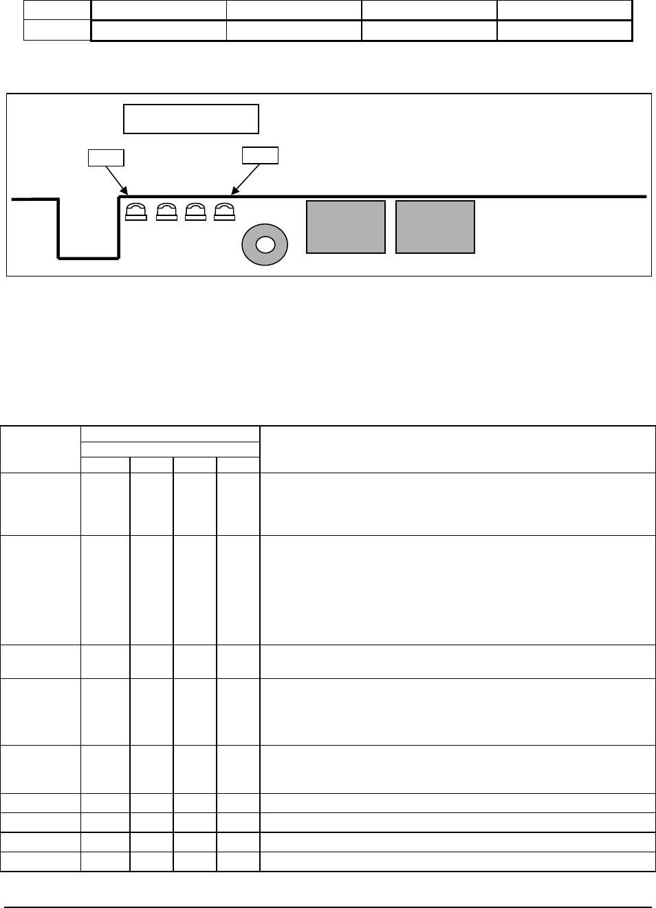
Figure 24. Location of Diagnostic LEDs on Baseboard
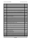
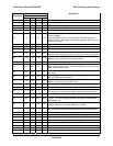
6.5.3 POST Code Checkpoints
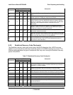
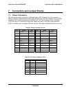
Table 75: POST Code Checkpoints
Diagnostic LED Decoder
G=Green, R=Red, A=Amber
Checkpoint
MSB LSB
Description
03 OFF OFF G G
Disable NMI, parity, video for EGA, and DMA controllers. Initialize
BIOS, POST, Run-time data area. Initialize BIOS modules on POST
entry and GPNV area. Initialized CMOS as mentioned in the Kernel
Variable "wCMOSFlags."
04 OFF G OFF OFF
Check CMOS diagnostic byte to determine if battery power is OK and
CMOS checksum is OK. Verify CMOS checksum manually by reading
storage area. If the CMOS checksum is bad, update CMOS with
power-on default values and clear passwords. Initialize status register
A.
Initializes data variables that are based on CMOS setup questions.
Initializes both the 8259 compatible PICs in the system
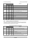
05 OFF G OFF G
Initializes the interrupt controlling hardware (generally PIC) and
interrupt vector table.
06 OFF G G OFF
Do R/W test to CH-2 count reg. Initialize CH-0 as system timer. Install
the POSTINT1Ch handler. Enable IRQ-0 in PIC for system timer
interrupt.
Traps INT1Ch vector to "POSTINT1ChHandlerBlock."
08 G OFF OFF OFF
Initializes the CPU. The BAT test is being done on KBC. Program the
keyboard controller command byte is being done after Auto detection
of KB/MS using AMI KB-5.
C0 R R OFF OFF Early CPU Init Start -- Disable Cache - Init Local APIC
C1 R R OFF G Set up boot strap processor Information
C2 R R G OFF Set up boot strap processor for POST
C5 R A OFF G Enumerate and set up application processors
LSB
MSB
Diagnostic LEDs
Back edge of baseboard