


Connectors and Jumper Blocks Intel® Server Board SE7520JR2
Revision 1.0
C78844-002
186
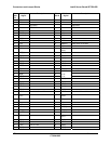
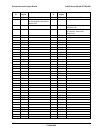
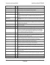
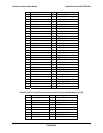
FMC Signal Name FMC
Pin
Description
LAN_I2C_3VSB_SCL 58 LAN usage
HDD_FLT_LED_N 64 Drive Fault LED output driven when FMM detects a bad drive from the Hot
Swap controller on the Hot Swap disk Drive sub-system.
FMM_PS_PWR_ON_N 65 Power On Request to the system Power Supply
COOL_FLT_LED_N 66 Cool Fault LED output driven when FMM detects a bad Fan if SSI front panel is
detect.
FMM_CPU_VRD_EN 67 This signal is driven by the FMM to enable the CPU VRDs and allow the VRD
power good chain to complete. This signal can also be used to keep the system
in reset for an extended time, beyond what the chipset RST_BTN_N can
provide.
FMM_SCI_N 68 SCI event request. If ACPI EC is supported by FMM, this signal is used for ACPI
interrupts.
ICH_PWR_BTN_N 69 FMM pass through of Front panel power button to chipset
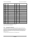
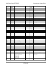
FMM_SPKR_N 72 FMM uses this to create Beep Codes on the system audible alarm. This signal is
configured as an Open Drain buffer in the FMM and must be pulled up to 3.3V
Standby on the motherboard
FP_NMI_BTN_N 73 NMI / Diagnostic interrupt from front panel. Actual NMI generated by SMBUS
command to mBMC
FP_SLP_BTN_N 74 Front panel Sleep Button input, if used
FP_ID_BTN_N 75 Front panel ID button, will cause the ID light to toggle
SYS_PWR_GD 76 Signal from the end of the baseboard VRD Power good chain. This signal
should be the last VRD power good indication generated on the baseboard.
Usually this would be the signal feeding the Chipset Power OK input. Used by
FMM in conjunction with RST_PWRGD_PS to determine if all critical VRDs
have successfully reached their nominal value.
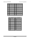
CPU2_SKTOCC_N 80 Indicates that a Processor is in the application processor socket
CLK_32K_RTC 81 This signal is used for “Synchronized clock with system RTC”. FMM can
synchronize own RTC with system RTC. IPMI define synchronized method.
clock comes from the Chipset RTC function.
CPU1_SKTOCC_N 82 Indicates that a Processor is in the primary processor socket. If this socket is
detected empty and there’s an attempt to power up the system, the FMM will
output an Error Beep Code and prevent the System from turning on
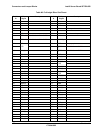
FMM_SOUT 85 EMP/SOL Serial Data Out. This is the Serial Port data output from FMM and
should be connected to the SIN signal in the SIO3 device
FMM_SIN 86 EMP/SOL Serial Data In. This is the Serial Port data input into the FMM and
should be connected to the SOUT signal in the SIO3 device
FMM_DCD_N 87 EMP/SOL Data Carrier Detect. This is the Serial Port Data Carrier Detect input
into the FMM and should be connected to the DCD signal in the SIO3 device
FMM_RTS_N 88 EMP/SOL Request to Send. This is the Serial Port Request to Send output from
FMM and should be connected to the CTS (Clear to Send) signal in the SIO3
device
FMM_DTR_N 89 EMP/SOL Data Terminal Ready. This is the Serial Port Data Terminal Ready
output from FMM and should be connected to the DSR (Data Set Ready) signal
in the SIO3 device
FMM_CTS_N 90 EMP/SOL Clear to Send. This is the Serial Port Clear to Send input into the
FMM and should be connected to the RTS (Ready to Send) signal in the SIO
device
ICMB_RX 93 Inter Chassis Communication Management Bus receive data
ICMB_TX 94 Inter Chassis Communication Management Bus transmit data
ICMB_TX_EN 96 Inter Chassis Communication Management Bus transceiver enable