


Server Board Overview Intel® Server Board SE7520JR2
Revision 1.0
C78844-002
22
o RJ45 Serial B Port
o Two RJ45 NIC connectors
o 15-pin video connector
o Two USB 2.0 ports
o U320 High density SCSI connector (Channel B) (SCSI SKU only)
• Internal IO Connectors / Headers
o Two onboard USB port headers. Each header is capable of supporting two USB
2.0 ports.
o One 10-pin DH10 Serial A Header
o One Ultra320 68-pin SCSI Connector (Channel A) (SCSI SKU only)
o Two SATA connectors with integrated chipset RAID 0/1 support
o One ATA100 connector
o One floppy connector
o SSI-compliant (34-pin) and custom control panel headers (50-pin and 100-pin)
o SSI-compliant 24-pin main power connector. This supports ATX-12V standard in
the first 20 pins
o Intel® Management Module (IMM) connector supporting both Professonal Edition
and Advanced Edition management modules
• Intel
®
Light-Guided Diagnostics on all FRU devices (processors, memory, power)
• Port-80 Diagnostic LEDs displaying POST codes
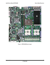
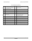
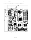
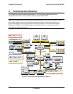
The following figure shows the board layout of the Server Board SE7520JR2. Each connector
and major component is identified by number and is identified in Table 1.