


Intel® Server Board SE7520JR2 Connectors and Jumper Blocks
Revision 1.0
C78844-002
179
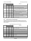
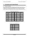
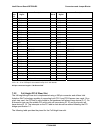
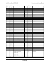
Pin-
Side
B
PCI Spec
Signal
Description Pin-
Side A
PCI Spec
Signal
Description
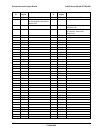
24 AD[57] 24 GND
23 GND 23 AD[56]
22 AD[55] 22 AD[54]
21 AD[53] 21 V (I/O) 3.3V or 1.5V
20 GND 20 AD[52]
19 AD[51] 19 AD[50]
18 AD[49] 18 GND
17 V (I/O) 3.3V or 1.5V 17 AD[48]
16 AD[47] 16 AD[46]
15 AD[45] 15 GND
14 GND 14 AD[44]
13 AD[43] 13 AD[42]
12 AD[41] 12 V (I/O) 3.3V or 1.5V
KEYWAY KEYWAY
KEYWAY KEYWAY
11 GND 11 AD[40]
10 AD[39] 10 AD[38]
9 AD[37] 9 GND
8 V (I/O) 3.3V or 1.5V 8 AD[36]
7 AD[35] 7 AD[34]
6 AD[33] 6 GND
5 GND 5 AD[32]
4 4
3 PRSNT_N 0=Riser Present 3 GND
2 GND 2
1 Size 0=1U, 1= 2U 1 GND
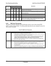
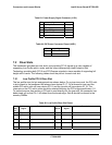
5V = 12 = 12 or 6 amps 3 slots needs 6 amps for 3 10W boards
3.3V= 19 = 19 or 9.5 amps 3 slots needs 9 amps for 3 10W boards
202 pin connector length = 139.45mm=5.49”
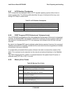
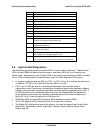
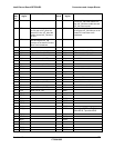
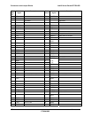
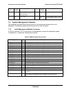
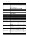
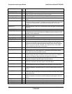
7.2.2 Full Height PCI-X Riser Slot
The full-height/length riser slot is implemented using a 280-pin connector and utilizes Intel
Adaptive Slot Technology capable of supporting both PCI-X and PCI-Express riser cards. On a
given riser card, the PCI add-in slot closest to the baseboard will always have device ID 17. On
a three-slot riser card the middle PCI add-in slot will have device ID 18, and the top slot will
have device ID 19. The interrupts on the PCI add-in slots should be rotated following the PCI
bridge specification 1.0.
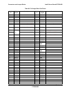
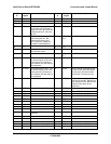
The following table provides the pinout for the Full Height riser slot.