


Intel® Server Board SE7520JR2 Connectors and Jumper Blocks
Revision 1.0
C78844-002
183
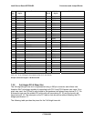
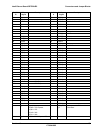
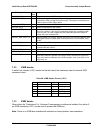
Pin-Side
B
PCI Spec
Signal
Description Pin-Side
A
PCI Spec
Signal
Description
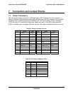
38 Ground 38 AD[02]
37 AD[01] 37 AD[00]
36 +3.3V Was Vio 3.3V or 1.5V 36 +3.3V Was Vio 3.3V or 1.5V
35 ACK64# 35 REQ64#
34 +5V 34 +5V
33 +5V 33 +5V
32 Reserved 32 +5V Was gnd
31 Ground 31 C/BE[7]#
30 C/BE[6]# 30 C/BE[5]#
29 C/BE[4]# 29 Ground Was VIO
28 Ground 28 PAR64
27 AD[63] 27 AD[62]
26 AD[61] 26 3.3V Was GND
25 3.3V 25 AD[60]
24 AD[59] 24 AD[58]
23 AD[57] 23 Ground
22 Ground 22 AD[56]
21 AD[55] 21 AD[54]
20 AD[53] 20 3.3V
19 Ground 19 AD[52]
18 AD[51] 18 AD[50]
17 AD[49] 17 Ground
16 3.3V 16 AD[48]
15 AD[47] 15 AD[46]
14 AD[45] 14 Ground
13 Ground 13 AD[44]
12 AD[43] 12 AD[42]
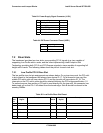
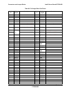
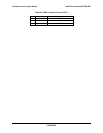
KEY Reversed PCI-Express KEY
KEY Reversed PCI-Express KEY
11 AD[41] 11 3.3V V
10 Ground 10 AD[40]
9 AD[39] 9 AD[38]
8 AD[37] 8 Ground
7 3.3V 7 AD[36]
6 AD[35] 6 AD[34]
5 AD[33] 5 Ground
4 Ground 4 AD[32]
3 Type1 Type(1:0)
(1U)00 = PCI-Express,
(1U)01 = PCI
(1U)10 = N/A
(1U)11 = N/A
3 PXH_RST
_N
Input to reset the PXH on the
active Riser
2 Type0 (2U)00=2xPCI-Express+PCI 2 Ground