


Intel® Server Board SE7520JR2 Connectors and Jumper Blocks
Revision 1.0
C78844-002
175
7. Connectors and Jumper Blocks
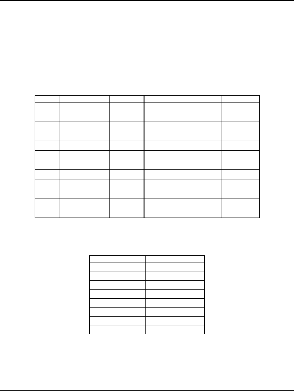
7.1 Power Connectors
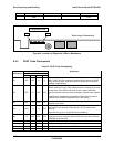
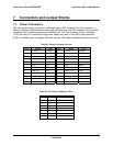
The main power supply connection is obtained using a SSI Compliant 2x12 pin connector. In
addition, there are three additional power related connectors; one SSI compliant 2x4 pin power
connector (J4J1) providing support for additional 12V, one SSI compliant 1x5 pin connector
(J1G1) providing I
2
C monitoring of the power supply, and one 1x2 pin IDE power connector
(U2E1) providing power to support IDE flash devices. The following tables define their pin-outs
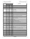
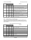
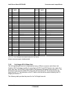
Table 81: Power Connector Pin-out
Pin Signal Color Pin Signal Color
1 +3.3Vdc Orange 13 +3.3Vdc Orange
2 +3.3Vdc Orange 14 -12Vdc Blue
3 GND Black 15 GND Black
4 +5Vdc Red 16 PS_ON# Green
5 GND Black 17 GND Black
6 +5Vdc Red 18 GND Black
7 GND Black 19 GND Black
8 PWR_OK Gray 20 RSVD_(-5V) White
9 5VSB Purple 21 +5Vdc Red
10 +12Vdc Yellow 22 +5Vdc Red
11 +12Vdc Yellow 23 +5Vdc Red
12 +3.3Vdc Orange 24 GND Black
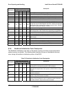
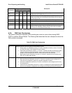
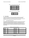
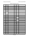
Table 82: 12V Power Connector (J4J1)
Pin Signal Color
1 GND
2 GND
3 GND
4 GND
5 +12Vdc
6 +12Vdc
7 +12Vdc
8 +12Vdc