


Intel® Server Board SE7520JR2 Connectors and Jumper Blocks
Revision 1.0
C78844-002
195
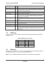
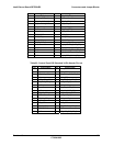
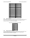
Pin Signal Name Pin Signal Name
1 RST_IDE_P_L 2 GND
3 IDE_PDD_7 4 IDE_PDD_8
5 IDE_PDD_6 6 IDE_PDD_9
7 IDE_PDD_5 8 IDE_PDD_10
9 IDE_PDD_4 10 IDE_PDD_11
11 IDE_PDD_3 12 IDE_PDD_12
13 IDE_PDD_2 14 IDE_PDD_13
15 IDE_PDD_1 16 IDE_PDD_14
17 IDE_PDD_0 18 IDE_PDD_15
19 GND 20 KEY
21 IDE_PDDREQ 22 GND
23 IDE_PDIOW_L 24 GND
25 IDE_PDIOR_L 26 GND
27 IDE_PIORDY 28 GND
29 IDE_PDDACK_L 30 GND
31 IRQ_IDE_P 32 Test Point
33 IDE_PDA1 34 IDE_CBL_DET_P
35 IDE_PDA0 36 IDE_PDA2
37 IDE_PDCS1_L 38 IDE_PDCS3_L
39 IDE_PRI_HD_ACT_L 40 GND
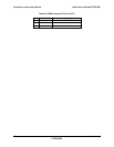
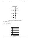
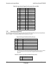
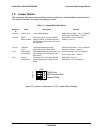
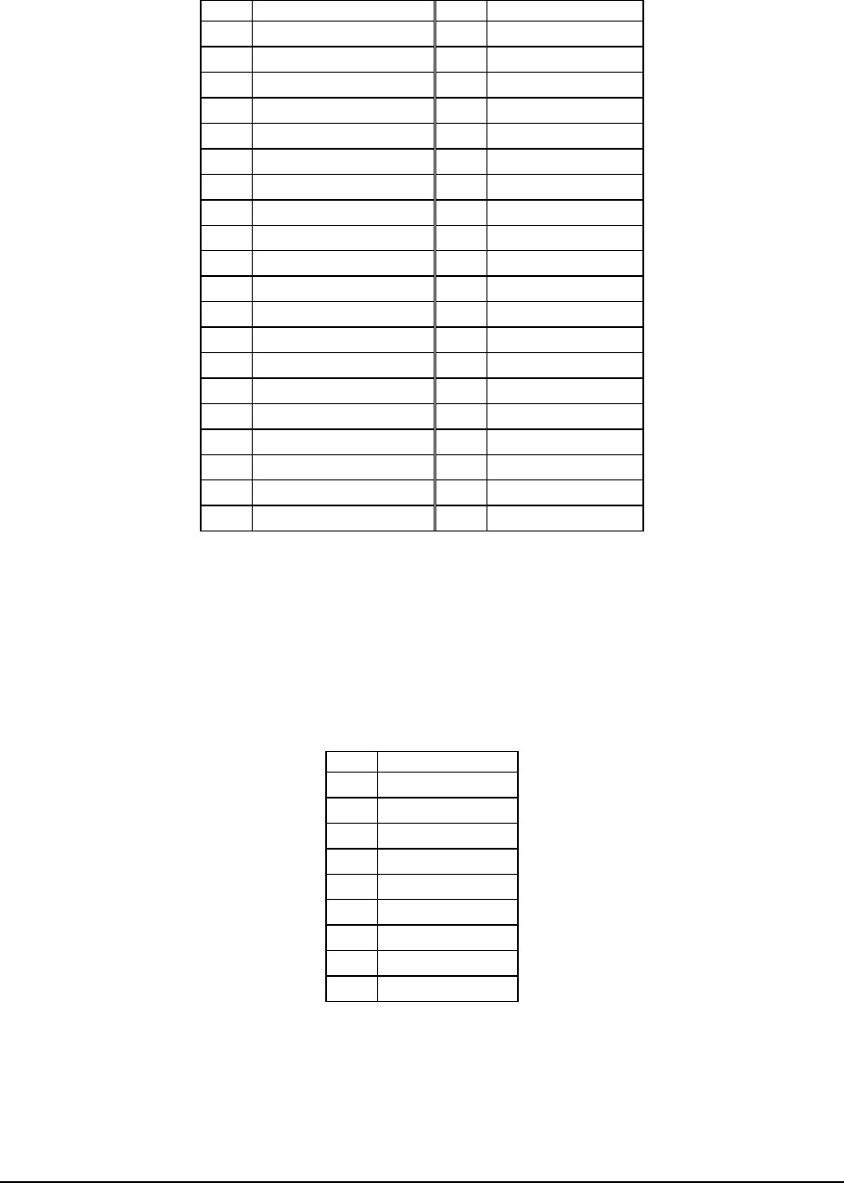
7.5.5 SATA Connectors
The Server Board SE7520JR2 provides two SATA (Serial ATA) connectors: SATA-0 (J1H1) and
SATA-1 (J1H5), for use with an internal SATA backplane. The pin configuration for each
connector is identical and is defined in the following table.
Table 98: SATA Connector Pin-out (J1H1 and J1H5)
Pin Signal Name
1 GND1
2 S_ATA#_TX_P
3 S_ATA#_TX_N
4 GND2
5 S_ATA#_RX_N
6 S_ATA#_RX_P
7 GND3
8 GND4
9 GND5
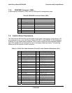
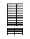
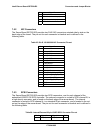
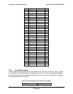
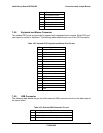
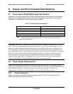
7.5.6 Floppy Controller Connector
The following table details the pin-out of the 34-pin legacy floppy drive connector (J3K2). These
signals are common to those used in the high-density 100-pin Front Panel connector.
Concurrent use of these connectors is not supported.