


Intel® Server Board SE7520JR2 Connectors and Jumper Blocks
Revision 1.0
C78844-002
193
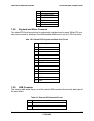
Pin Signal Name
12 DDCDAT
13 HSYNC (horizontal sync)
14 VSYNC (vertical sync)
15 DDCCLK
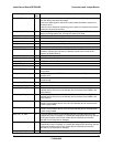
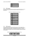
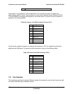
7.5.2 NIC Connectors
The Server Board SE7520JR2 provides two RJ45 NIC connectors oriented side by side on the
back edge of the board. The pin-out for each connector is identical and is defined in the
following table:
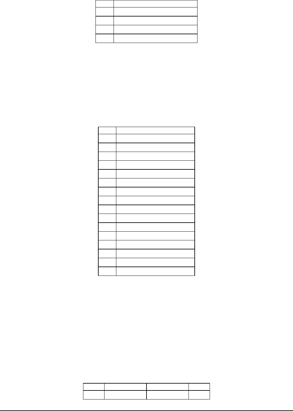
Table 95: RJ-45 10/100/1000 NIC Connector Pin-out
Pin Signal Name
1
2 LAN_MID0P
3 LAN_MID0N
4 LAN_MID1P
5 LAN_MID2P
6 LAN_MID2N
7 LAN_MID1N
8 LAN_MID3P
9 LAN_MID3N
10 P2V5_NIC
11 LAN_LINK_1000_L (LED)
12 LAN_LINK_100_L_R (LED)
13 LAN_ACT_L (LED)
14 LAN_LINK_L_R (LED)
15 GND
16 GND
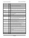
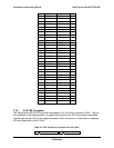
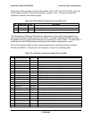
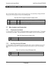
7.5.3 SCSI Connectors
The Server Board SE7520JR2 provides two SCSI connectors, one for each channel of the
embedded LSI53C1030 SCSI controller. The external connector is routed to SCSI channel B, is
a high density connector, and is found on the back edge of the server board. The internal
connector is routed to SCSI channel A, is a standard 68 pin connector, and is located in the cut-
out on the edge of the server board. The pin-out for each connector is identical and is defined in
the following table.
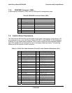
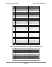
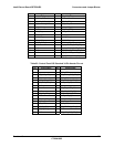
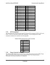
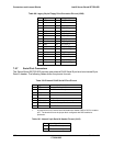
Table 96: Internal/External 68-pin VHDCI SCSI Connector Pin-out
Pin# Signal Name Signal Name Pin#
1 +DB(12) -DB(12) 35