


Connectors and Jumper Blocks Intel® Server Board SE7520JR2
Revision 1.0
C78844-002
176
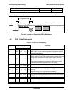
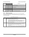
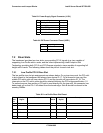
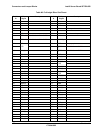
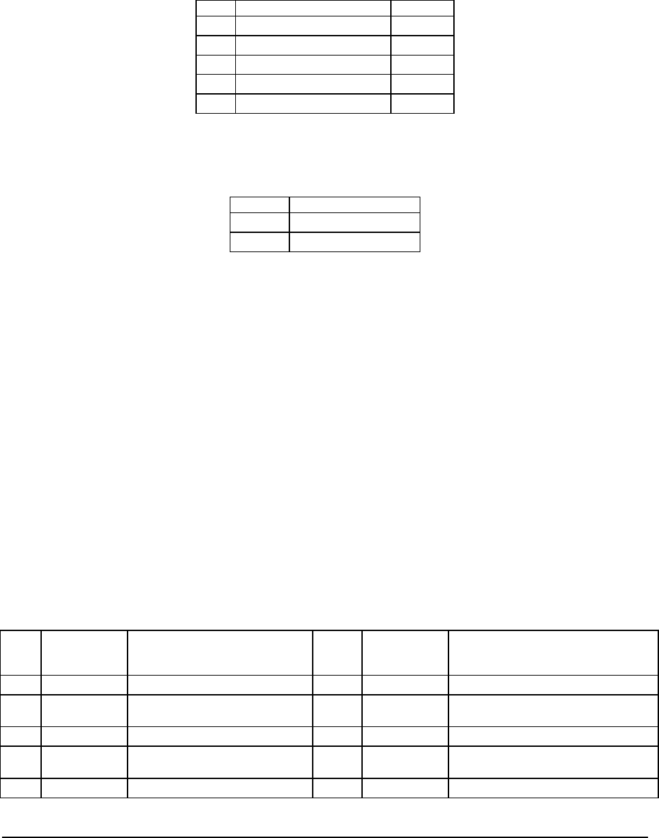
Table 83: Power Supply Signal Connector (J1G1)
Pin Signal Color
1 5VSB_SCL Orange
2 5VSB_SDA Black
3 PS_ALTER_L, Not used Red
4 3.3V SENSE- Yellow
5 3.3V SENSE+ Green
Table 84: IDE Power Connector Pinout (U2E1)
Pin Signal
1 GND
2 5V VCC
7.2 Riser Slots
The baseboard provides two riser slots; one providing PCI-X signals to a riser capable of
supporting Low Profile add-in cards, and the other implementing Intel® Adaptive Slot
Technology providing both PCI-X and PCI-Express signals to risers capable of supporting full
height add-in cards. The following tables show the pin-out for each riser slot.
7.2.1 Low Profile PCI-X Riser Slot
The low profile riser slot pin assignments are shown below. On a given riser card, the PCI add-
in slot closest to the baseboard will always have device ID 17. On a three-slot riser card the
middle PCI add-in slot will have device ID 18, and the top slot will have device ID 19. The
interrupts on the PCI add-in slots should be rotated following the PCI bridge specification 1.0.
To prevent anyone from putting a PCI add-in card directly into the riser slot, the connector has
been pined out so that Pin 1 is furthest from the board edge. Side B should be closest to the
memory DIMMs.
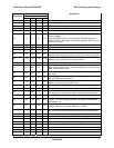
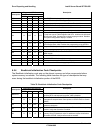
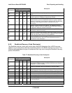
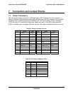
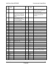
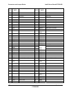
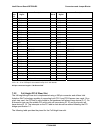
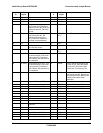
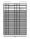
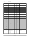
Table 85: Low Profile Riser Slot Pinout
Pin-
Side
B
PCI Spec
Signal
Description Pin-
Side A
PCI Spec
Signal
Description
101 -12V 101 RSVD
100 RSVD 100 +12V
99 GND 99 RSVD
98 RSVD 98 +5V
97 +5V 97 +5V