


Functional Architecture Intel® Server Board SE7520JR2
Revision 1.0
C78844-002
48
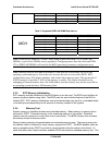
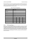
Table 7: PCI Bus Segment Characteristics
PCI Bus Segment Voltage Width Speed Type PCI I/O Card Slots
P32-A 5 V 32-bits 33 MHz PCI None. Internal component use only
P64-A 3.3 V 64-bits 100 MHz PCI-X
Common riser slot capable of supporting full-
length PCI-X or PCI-E add-in cards
P64-B 3.3 V 64-bits 100 MHz PCI-X
One riser slot supporting only low-profile add-
in cards
P64-Express Differential 64-bits Dual x4 PCI-E
Common riser slot capable of supporting full-
length PCI-X or PCI-E add-in cards
3.4.1.1 P32-A: 32-bit, 33-MHz PCI Subsystem
All 32-bit, 33-MHz PCI I/O is directed through the ICH5-R. The 32-bit, 33-MHz PCI segment
provided by the ICH5-R is known as the P32-A segment. The P32-A segment supports the
following embedded devices:
• 2D/3D Graphics Accelerator: ATI Rage XL Video Controller
• SIO Chip: National Semiconductor* PC87417 Super I/O
• Hardware monitoring sub-system: SMBUS
3.4.1.2 P64-A and P64-B: 64-bit, 100MHz PCI Subsystem
Two peer 64-bit PCI-X bus segments are directed through the PXH PCI Bridge. The first PCI-X
segment, P64-A, supports the interface for the on-board LSI* 53C1030 Ultra320 SCSI controller,
in addition to supporting up to three PCI-X add-in cards from the full-height PCI riser slot. The
second PCI-X segment, P64-B, supports the interface to the on-board Intel
®
82546GB dual port
Gigabit network controller, in addition to up to three PCI-X add-in cards from the low profile PCI
riser slot.
3.4.1.3 P64-Express: Dual x4 PCI Bus Segment
The full height riser slot supports both X4 and X8 PCI-E type widths. In a 2U system, the
baseboard supports two x4 PCI-E slots. In a 1U system, the baseboard supports one x8 PCI-E
slot.
The BIOS performs link training with PCI-E devices during boot and checks the resulting status.
If it detects that a port is not connected to a PCI-E device, it disables the port.
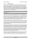
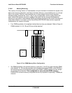
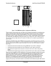
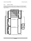
3.4.1.4 PCI Riser Slots
The Server Board SE7520JR2 has two riser slots capable of supporting riser cards for both 1U
and 2U system configurations. Because of board placement resulting in different pin
orientations, and expanded technology support associated with the full-height riser, the riser
slots are proprietary and require different riser cards.
The low profile riser slot (J5F1) utilizes a 202-pin connector. It is capable of supporting up to
three low profile PCI-X add-in cards, depending on the riser card used. The P64-B bus can
support bus speeds of up to 100MHz with up to two PCI-X 100MHz cards installed. The bus
speed will drop to 66MHz when three PCI-X 100MHz cards are installed, or will match the card
speed of the lowest speed card on the bus. Ie) If any of the add-cards installed on the P64B bus